DAF 95XF. Manual - part 834


  Index      DAF     DAF 95XF Series - service repair manual


Search            


Content   ..  832  833  834  835   ..


DAF 95XF. Manual - part 834


1

CAB SUSPENSION

Inspection and adjustment

3-4

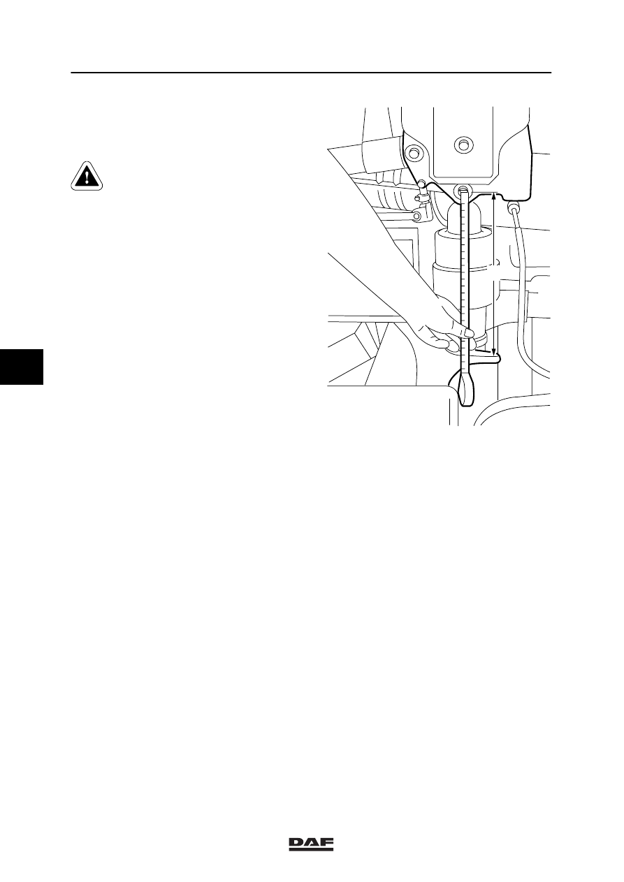
Inspecting and adjusting rear cab
suspension
1.

Bring the system up to maximum service
pressure.

Risk of being trapped when cab
suspension is vented.

2.

Vent the cab suspension using the height
control valves.

3.

Then allow the height control valve to raise
the cab to the proper height and measure
distance “B” between the top of the bracket
and the centre of the attachment bolt.

4.

If this height must be adjusted, loosen the
attachment bolts of the height control valve.
After this, the height can be adjusted by
changing the position of the valve. For the
setting value, see “Technical Data”.

Note:
The air bellows must be vented before each
new measurement. After this, the height control
valve will adjust to the set height.

K100349

B

5

ᓻ 0209

1

Removal and installation

CAB SUSPENSION

4-1

4. REMOVAL AND INSTALLATION

4.1 REMOVAL AND INSTALLATION, STABILISER BAR

When working on the cab
suspension provide extra supports
for the cab to avoid the risk of being
trapped.

Removing the stabiliser bar
1.

Remove the cab grille, lower grille and
corner pieces.

2.

Lift the cab at the front in such a way as to
make it possible to remove the cab bearing
pin.

3.

Bleed the reservoirs (only applies to air
suspension elements).

4.

Remove the pipes to allow grease
lubrication.

5.

Remove the grease lubrication connection
nipple (1).

6.

Using a drop stamp, remove the sealing
plug (2).

7.

Remove the locating bolt (3) from the
silentblock (4).

8.

Remove the locking bolt at the front of the
stabiliser bar.

9.

Remove the cab bearing pin (5) at the front.

10. Remove the stabiliser bar.

Installing the stabiliser bar
1.

Install the stabiliser bar and insert the
locating bolt (3) through the silentblock.

2.

Apply Loctite to the locating bolt and tighten
it to the specified tightening torque. See
“Technical data”.

8

6

8

7

7

1

2

5

10

(9)

3

4

11

K100821

5

ᓻ 0209

1

CAB SUSPENSION

Removal and installation

4-2

3.

Manufacture an assembly fork from thin
sheet metal (see figure) to facilitate the
installation of the cab suspension.

4.

Bring the cab bracket, stabiliser bar and
suspension element together in such a way
as to be able to install the cab bearing pin.
While installing, ensure that the recess in
the bearing pin aligns with the opening in
the locking bolt.

5.

Fit the locking bolt.

6.

Fit the sealing plug using a plastic hammer.

7.

Fit the grease lubrication connection nipple.

8.

Connect the grease lubrication pipes.

9.

Carefully tilt the cab back.

10. Fit the cab grille, lower grille and the corner

pieces around the headlights.

2

1

A

A

K100414

5

ᓻ 0209

1

Removal and installation

CAB SUSPENSION

4-3

4.2 REMOVAL AND INSTALLATION, CAB SUPPORT SILENTBLOCK

When working on the cab
suspension provide extra supports
for the cab to avoid the risk of being
trapped.

Removing cab support silentblock
1.

Remove the stabiliser bar.

2.

Remove the cab support(s) of the chassis

3.

Using the special tool (DAF no 1329401)
push the silentblock out of the support.

K100557

5

ᓻ 0209


Content   ..  832  833  834  835   ..