DAF 95XF. Manual - part 494


  Index      DAF     DAF 95XF Series - service repair manual


Search            


Content   ..  492  493  494  495   ..


DAF 95XF. Manual - part 494


3

DRIVE SHAFTS

Disassembly and assembly

4-10

4.3 DISASSEMBLY AND ASSEMBLY OF THE “KLEIN” CENTRE BEARING

Disassembling the “Klein” centre bearing
1.

Secure the auxiliary shaft to the chassis.

2.

Remove the bolts that attach the flange to
the drive shaft and the auxiliary shaft. Now
also secure the drive shaft to the chassis.

3.

Install a flange retainer and remove the
central nut and washer.
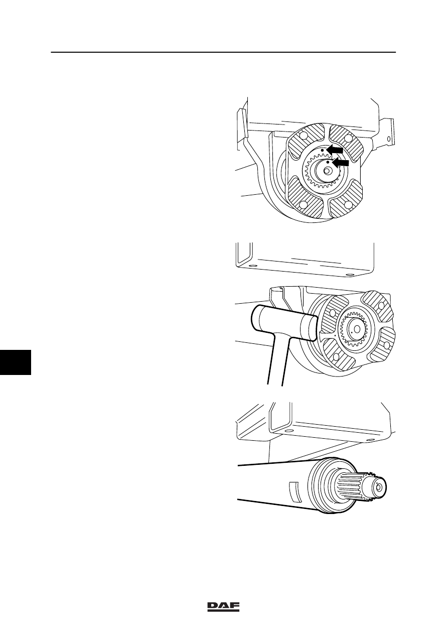
4.

Mark the flange and axle stub with a centre
point. This is to make it possible to reinstall
all forks in a straight line.

5.

Remove the fixing bolts from the centre
bearing and the chassis bracket.

6.

Use a plastic mallet to tap the flange and
the centre bearing from the auxiliary shaft.
If necessary, use a puller.

W 3 06 029

W 3 06 028

W 3 06 027

8

ǹ 0002

3

Disassembly and assembly

DRIVE SHAFTS

4-11

7.

Remove the lock plate from the support
bracket.

8.

Turn the flange, including bearing and
rubber block (2), from the bracket.

9.

Press the flange from the bearing using a
press.

10. Press the bearing with one dust ring (1)

from the rubber block.

11. If necessary, remove the second dust

ring (1).

Note:
In case of damage, always replace the entire
centre bearing.

W 3 06 020

W 3 06 022

W 3 06 023

1

2

3 1

4

5

8

ǹ 0002

3

DRIVE SHAFTS

Disassembly and assembly

4-12

Assembling the “Klein” centre bearing
1.

Press the dust ring into the bush of the
rubber block until it aligns with the outside
of the bush.

2.

Press the bearing into the bush from the
other side. Then press the other dust ring
into the bush. Apply grease to the dust
rings (1).

3.

Press everything onto the flange, the larger
space between bearing and dust ring facing
the flange.

W 3 06 021

W 3 06 025

1

8

ǹ 0002

3

Disassembly and assembly

DRIVE SHAFTS

4-13

4.

Install the centre bearing assembly in the
bracket and lock it with the lock plate.

5.

Install the centre bearing onto the auxiliary
shaft. Ensure that the centre marks match.
This is to make sure that all forks line up.

6.

Attach the centre bearing to the chassis by
means of bolts, but do not tighten the bolts
yet.

7.

Tighten the central nut of the centre bearing
to the specified tightening torque, see main
group “Technical Data”. Then apply
Loctite 243 to the fixing bolts of the centre
bearing at the chassis and tighten these to
the specified tightening torque, see main
group “Technical Data”.

W 3 06 024

W 3 06 029

W 3 06 018

8

ǹ 0002


Content   ..  492  493  494  495   ..