DAF 95XF. Manual - part 146


  Index      DAF     DAF 95XF Series - service repair manual


Search            


Content   ..  144  145  146  147   ..


DAF 95XF. Manual - part 146


6

Removal and installation

BRAKE COMPONENTS

2-23

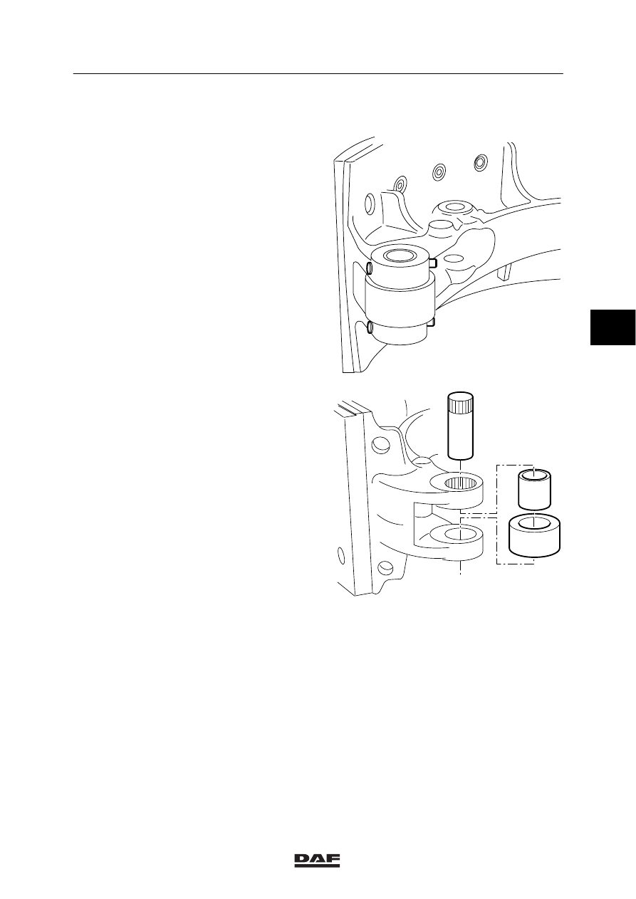
2.9 REMOVAL AND INSTALLATION, BRAKE-SHOE BEARING

ANCHOR-PIN BEARING

1.

Remove the brake shoes.

2.

Force the new bearing bushes into the
brake shoe. Check whether the anchor pins
can rotate in the new bearing bushes.

3.

Fit the brake shoes.

ROLLER-CAM BEARING

The axles for the roller-cam bearings can be
locked in two ways.

-

Locking by means of a spindle and two
spring pins.

-

Locking by means of a spindle with a
knurled edge.

R600148

R600149

4

ǹ 0006

6

BRAKE COMPONENTS

Removal and installation

2-24

For the model of the spindle with knurled edge,
the following should be remembered:

-

The first time the spindle with the knurled
edge is fitted is during production.
The spindle may be fitted a maximum of
THREE TIMES on ones side of the brake
shoe. Every time it is REINSTALLED, a
mark must be made on the brake shoe with
a centre point.
Two centre points indicate that the spindle
must be fitted in the REVERSE direction.
In this position too, the spindle may not be
fitted more than three times.
After the spindle is fitted three times on the
other side of the brake shoe, the brake
shoe MUST be renewed.

Removal of the roller-cam bearing
1.

Remove the brake shoes.

2.

If fitted, remove the spring pins.

3.

Force the spindle from the brake shoe. For
the version with the knurled edge, force the
spindle from the shoe in such a way that
the knurled edge is not forced through the
complete brake shoe.

Installation of the roller-cam bearing
1.

Check the brake shoe, spindle and roller
cam for damage. Replace if necessary.

2.

Force the new bearing bush into the roller
cam.

3.

Force the spindle into the brake shoe with
the roller cam. For the version of the
spindle with the knurled edge, mark the
spindle as indicated in this chapter.

4.

Fit the brake shoes.

R600150

4

ǹ 0006

6

Removal and installation

BRAKE COMPONENTS

2-25

2.10 REMOVAL AND INSTALLATION, BRAKE CAMSHAFT

Removal of the brake camshaft
1.

Remove the brake shoes.

2.

Remove the automatic slack adjuster.

3.

Disconnect the air pipe to the spring-brake
cylinder.

4.

Remove the attachment bolts from the
spring-brake cylinder bracket.

5.

Slide the spring-brake cylinder bracket
complete with the spring-brake cylinder
from the brake camshaft. Support the brake
camshaft during this process.

6.

Remove the brake camshaft from the back
plate.

7.

Check the brake camshaft. The curve
against which the rollers run should not be
worn or damaged.

R600151

R600152

4

ǹ 0006

6

BRAKE COMPONENTS

Removal and installation

2-26

Installation of the brake camshaft
1.

Before installation, first clean all parts and
lubricate them with Copaslip.

2.

Check the seals in the bracket. If
necessary, replace these.

3.

Insert the brake camshaft with the spacer
ring through the back plate, and slide the
spring-brake cylinder bracket complete with
spring-brake cylinder over the brake
camshaft.

4.

Tighten the spring-brake cylinder bracket
with the specified torque to the back plate,
see main group “Technical data”.

5.

Check the radial play. This must be
minimal. If necessary, replace the bearing
bush.

6.

Fit the brake shoes.

7.

Fit the automatic slack adjuster.

4

ǹ 0006


Content   ..  144  145  146  147   ..