DAF 95XF. Manual - part 139


  Index      DAF     DAF 95XF Series - service repair manual


Search            


Content   ..  137  138  139  140   ..


DAF 95XF. Manual - part 139


6

Inspection and adjustment

BRAKE COMPONENTS

1-39

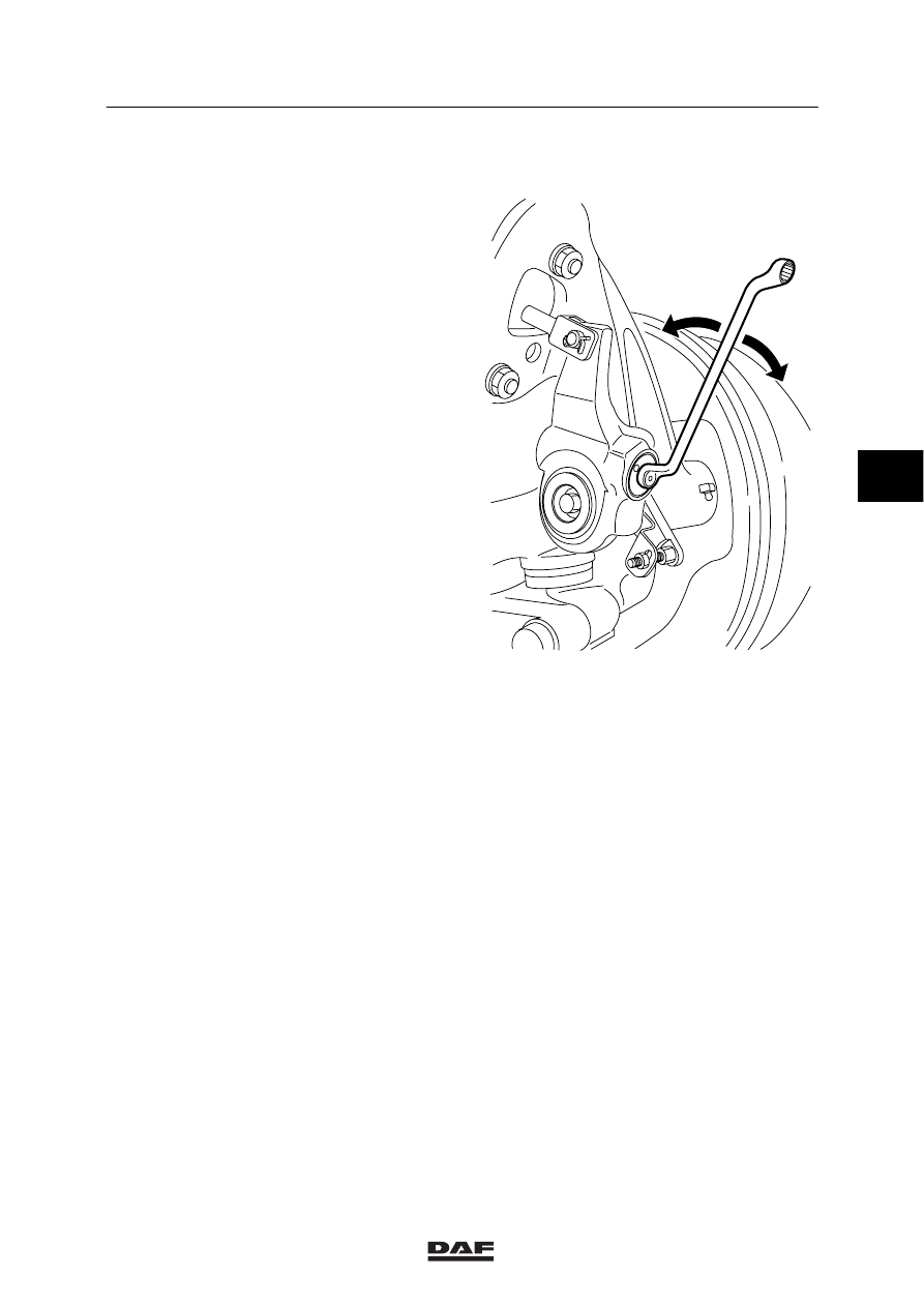
1.20 BRAKE ADJUSTMENT

1.

Set the brakes by turning the adjusting
hexagon-head bolt clockwise.

2.

Turn the adjusting bolt until the brake lining
is square against the brake drum.

3.

Then turn the adjusting bolt back
(90

_ - 120_) until the bake lining is free

from the brake drum.

R600253

1.21 INSPECTION FOR AIR-TIGHTNESS

Air-tightness
If the brake system of a vehicle has been
charged to the maximum pressure, it should
generally be possible to drive the vehicle away
after a period of 16 hours of uninterrupted
standstill, without having to first charge the
brake system to sufficient operating pressure.
This comes down to a maximum pressure drop
of approx. 0.4 bar per hour at a normal system
pressure.
Note:
Auxiliary consumers and accessories must only
be connected to circuit 4.

4

ǹ 0006

6

BRAKE COMPONENTS

Inspection and adjustment

1-40

1.22 INSPECTION OF BALANCING FRONT AND REAR AXLES OF THE

TRACTOR

Depending on the superstructure of the vehicle,
the lining wear between the various axles will
vary. In case of an inadvertent superstructure, a
difference of 100% is admissible.
If the difference exceeds this percentage, act as
follows:

First check the correct setting of the
load-sensing valve. If required, follow the
adjusting procedure. Always use reliable
gauges. Check this reliability by repeating the
first measurement, switching both gauges.

Note:
Automatic load-sensing valves as applied at
leaf-spring suspension cannot be adjusted
correctly for an unloaded vehicle leaving the
factory. Because of the “swelling” of the springs,
this should always be checked and/or corrected
during the first service inspection.

Next, carry out a measurement as described
below.

-

Connect pressure gauges to the rear and
front axle brake chambers.

-

Set the automatic load-sensing valve at
maximum (lever at maximum upward
position or, in case of air suspension, min.
6 bar at simulation connection No. 43).

Now measure the front-axle braking pressures
at the reference values in the following table
(remember the reliability of the gauges).

Rear axle
braking
pressure

0.5

0.8

1.0

1.5 2.0 3.0

Front-axle
braking
pressure
First
measurement

...

...

...

...

...

...

Second
measurement

...

...

...

...

...

...

3

2 L

1

M6106

42

1

2

4

2

4

41

43

M6102

4

ǹ 0006

6

Inspection and adjustment

BRAKE COMPONENTS

1-41

The braking pressures measured should be
equal at 1 bar. This in view of hysteresis, i.e.
tolerances of the various valves. At a pressure
of 1 bar these tolerances are almost equal. In
case of deviations, three different situations can
arise:

-

The rear-axle pressure exceeds the
front-axle pressure.

-

The front-axle pressure exceeds the
rear-axle pressure.

-

Complaints about braking performance in
spite of equal braking pressures.

The rear-axle pressure exceeds the
front-axle pressure
If the differential pressure is considerable
(0.35 bar or more), this will cause increased
lining wear on the rear axle.
Furthermore, if the vehicle is not fitted with ABS,
there is a danger of the rear wheels blocking too
soon causing the rear axle to skid outwards. On
vehicle combinations, this may result in
jack-knifing.

Possible solutions are:
-

Using the setting tolerances of the
automatic load-sensing valve (

 0.2 bar at

the braking pressure and, in case of air
suspension,

+ 0.2 bar at the bellows

pressure) to reduce the rear-axle pressure,
thus improving the front/rear axle balancing

-

If this does not give sufficient improvement,
the rear-axle braking pressure may be
reduced by fitting check valve
DAF no. 0291686 in port (4) of the
automatic load-sensing valve (see drawing).

-

If necessary, the check action of this valve
may be reduced by removing one or more
rings from the valve, or by shortening the
spring inside the valve.

Note:
After a braking-pressure adjustment has been
made, the braking pressure of the axles must be
checked again (see the previous page). Check
setting(s) and wear pattern during the next
service inspection.

R600040

4

ǹ 0006

6

BRAKE COMPONENTS

Inspection and adjustment

1-42

The front-axle pressure exceeds the
rear-axle pressure
If the differential pressure is considerable
(0.2 bar or more), this will cause increased lining
wear on the front axle.
Possible solutions are:

-

On 10-bar systems, the factory-fitted relay
valve (DAF no. 1333733) (W 973 011 008
0) in the front axle circuit can be replaced
by a version with a spring under the
regulating piston (DAF no. 1340470)
(W 973 011 009 0), reducing front-axle
braking pressure by 0.5 bar (see figure).

R600041

Type

Empty/load relay valve

(with increase of control pressure)

Maximum

reduction ratio

FA 95

XF

(W 973 011 109 0)

DAF no. 1340471

1:1.5

FAC 95

XF

(W 973 011 110 0)

DAF no. 1350673

1:2.7

FAR/FAS 95

XF

(W 973 011 109 0)

DAF no. 1340471

1:1.5

FAT 95

XF

with 1355T

(W 973 011 109 0)

DAF no. 1340471

1:1.5

FAD 95

XF

with 1355T

(W 973 011 110 0)

DAF no. 1350673

1:2.7

If desired, the idle relay valve of vehicles not yet
equipped with the idle relay valve with increase
of control pressure can be adapted. The control
pressure can be increased by installing a spring
(DAF no. 1342405) directly below the regulating
piston of the idle relay valve.

-

Less rear-axle braking can also be
achieved by means of fitting an extra return
spring between the brake shoes.

4

ǹ 0006


Content   ..  137  138  139  140   ..