Chrysler Sebring, Stratus sedan, Sebring Convertible. Manual - part 743


  Index      Chrysler     Chrysler Sebring, Stratus sedan, Sebring Convertible - service repair manual 2001-2007 year


Search            


Content   ..  741  742  743  744   ..


Chrysler Sebring, Stratus sedan, Sebring Convertible. Manual - part 743


(1) Connect a charging station or manifold gauge

set to the refrigerant system service ports. Verify the
refrigerant charge level.

(2) Close all doors, windows and vents to the pas-

senger compartment.

(3) Set the A/C-heater controls so that the A/C

compressor is operating, the temperature control is
in the highest temperature position, the mode-air
doors is directing air output to the floor and the
blower motor operating is operating at the highest
speed.

(4) Start the engine and allow it to idle. After the

engine has reached normal operating temperature,
allow the passenger compartment to heat up. This
will create the need for maximum refrigerant flow
into the A/C evaporator.

(5) If the refrigerant charge is sufficient, the dis-

charge (high pressure) gauge should read 827 kPa to
1655 kPa (120 psi to 240 psi). The suction (low pres-
sure) gauge should read 207 kPa to 345 kPa (30 psi
to 50 psi). If OK, go to Step 6. If not OK, replace the
faulty A/C expansion valve.

WARNING:
Protect the skin and eyes from exposure to liquid
CO

2

or personal injury can result.

(6) If the suction (low pressure) gauge reads

within the specified range, freeze the A/C expansion
valve for 30 seconds using liquid CO

2

or another suit-

able super-cold material.Do not spray R-134a or
R-12 refrigerant on the A/C expansion valve for
this test. 
The suction (low pressure) gauge reading
should drop by 69 kPa (10 psi). If OK, go to Step 7 If
not OK, replace the faulty A/C expansion valve.

(7) Allow the expansion valve control head to thaw.

The suction (low pressure) gauge reading should sta-
bilize at 207 kPa to 345 kPa (30 psi to 50 psi). If not
OK, replace the faulty A/C expansion valve.

(8) When expansion valve testing is complete, test

the overall A/C system performance (Refer to 24 -
HEATING & AIR CONDITIONING - DIAGNOSIS
AND TESTING - A/C PERFORMANCE TEST).

REMOVAL

WARNING: Refer to the applicable warnings and
cautions for this system before performing the fol-
lowing operation (Refer to 24 - HEATING & AIR
CONDITIONING/PLUMBING - WARNINGS) and (Refer
to 24 - HEATING & AIR CONDITIONING/PLUMBING -
CAUTIONS). Failure to follow the warnings and cau-
tions could result in possible personal injury or
death.

(1) Recover the refrigerant from the refrigerant

system (Refer to 24 - HEATING & AIR CONDITION-

ING/PLUMBING

-

STANDARD

PROCEDURE

-

REFRIGERANT SYSTEM RECOVERY).

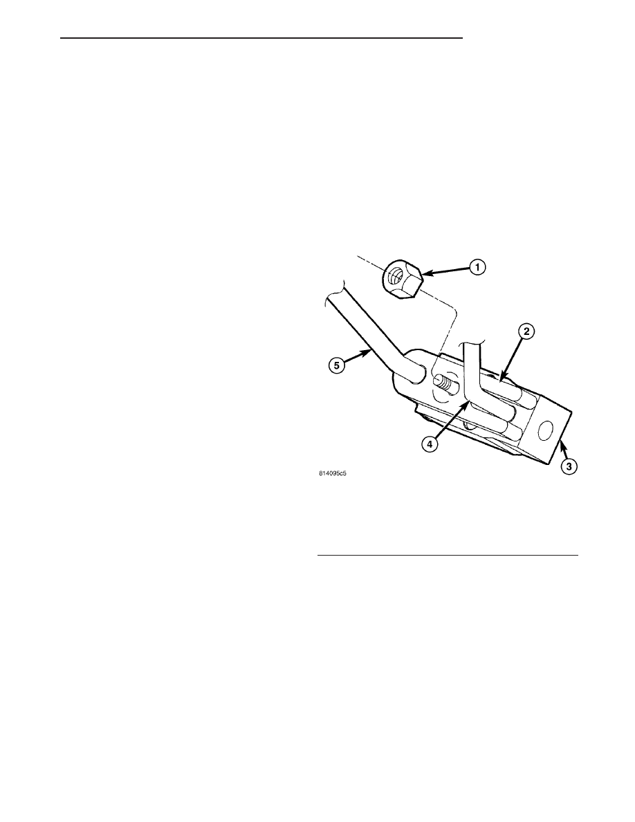
(2) Remove the bolt that secures the refrigerant

line retainer bracket to the right shock tower.

(3) Remove the nut that secures the refrigerant

line tapping plate to the A/C expansion valve (Fig.
16).

(4) Disconnect the A/C suction line and the A/C liq-

uid line from the A/C expansion valve and position
the refrigerant lines out of the way.

(5) Remove the O-ring seal from the suction and

liquid line fittings and discard.

(6) Install plugs in, or tape over the opened suc-

tion and liquid line fittings.

(7) Remove the two bolts that secure the A/C

expansion valve to the evaporator tube tapping plate
(Fig. 17).

(8) Remove the A/C expansion valve from the evap-

orator tube tapping plate.

(9) Remove the O-ring seals from the evaporator

tube fittings and discard.

(10) Install plugs in, or tape over the opened evap-

orator tube fittings and all expansion valve ports.

(11) Remove expansion valve.

INSTALLATION

(1) Remove the tape or plugs from the evaporator

tube fittings and all of the expansion valve ports.

(2) Lubricate new rubber O-ring seals with clean

refrigerant oil and install them on to the evaporator
tube fittings. Use only the specified O-rings as they

Fig. 16 A/C Expansion Valve-Tapping Plate

1 - NUT
2 - TAPPING PLATE
3 - A/C EXPANSION VALVE
4 - A/C LIQUID LINE
5 - A/C SUCTION LINE

JR

PLUMBING

24 - 71

A/C EXPANSION VALVE (Continued)

are made of a special material for the R-134a system.
Use only refrigerant oil of the type recommended for
the A/C compressor in the vehicle.

(3) Install the A/C expansion valve onto the evap-

orator tube tapping plate.

(4) Install the two bolts that secure the A/C expan-

sion valve to the evaporator tube tapping plate.
Tighten the bolts to 11 N·m (97 in. lbs.).

(5) Remove the tape or plugs from the suction and

liquid line fittings.

(6) Lubricate new O-ring seals with clean refriger-

ant oil and install them onto the suction and liquid
line fittings. Use only the specified seal as it is made
of a special material for the R-134a system. Use only
refrigerant oil of the type recommended for the A/C
compressor in the vehicle.

(7) Connect the A/C suction line and the A/C liquid

line to the A/C expansion valve.

(8) Install the nut that secures the refrigerant line

tapping plate to the A/C expansion valve. Tighten the
nut to 23 N·m (17 ft. lbs.).

(9) Position the refrigerant line retainer bracket to

the right shock tower and install the bolt securely.

(10) Evacuate the refrigerant system (Refer to 24 -

HEATING & AIR CONDITIONING/PLUMBING -
STANDARD PROCEDURE - REFRIGERANT SYS-
TEM EVACUATE).

(11) Charge the refrigerant system (Refer to 24 -

HEATING & AIR CONDITIONING/PLUMBING -
STANDARD PROCEDURE - REFRIGERANT SYS-
TEM CHARGE).

HEATER CORE

DESCRIPTION

The heater core (Fig. 18) is located in the HVAC

housing, behind the instrument panel. The heater
core is a heat exchanger made of rows of tubes and
fins. The heater core tubes are attached to the side of
the heater core and cannot be serviced separately.

OPERATION

Engine coolant is circulated through the heater

hoses to the heater core at all times. As the coolant
flows through the heater core, heat is removed from
the engine and is transferred to the heater core tubes
and fins. Air directed through the heater core picks
up the heat from the heater core fins. The blend-air
door allows control of the heater output air tempera-
ture by regulating the amount of air flowing through
the heater core. The blower motor speed controls the
volume of air flowing through the HVAC housing.

The heater core cannot be repaired and, if faulty or

damaged, it must be replaced.

Fig. 17 A/C Expansion Valve

1 - EVAPORATOR SEAL
2 - A/C EXPANSION VALVE
3 - HVAC HOUSING
4 - HEATER CORE TUBES
5 - HVAC HOUSING STUD
6 - HVAC HOUSING STUD
7 - EXPANSION VALVE BOLT (2)

Fig. 18 Heater Core

1 - HEATER CORE
2 - INLET TUBE
3 - OUTLET TUBE

24 - 72

PLUMBING

JR

A/C EXPANSION VALVE (Continued)

REMOVAL

WARNING: On vehicles equipped with airbags, dis-
able the airbag system before attempting any steer-
ing wheel, steering column, or instrument panel
component diagnosis or service. Disconnect and
isolate the negative battery (ground) cable, then
wait two minutes for the airbag system capacitor to
discharge before performing further diagnosis or
service. This is the only sure way to disable the air-
bag system. Failure to take the proper precautions
could result in accidental airbag deployment and
possible personal injury or death.

(1) Remove the HVAC housing (Refer to 24 -

HEATING & AIR CONDITIONING/DISTRIBUTION/
HOUSING-HVAC - REMOVAL).

(2) Disassemble the HVAC housing as necessary to

access the heater core (Refer to 24 - HEATING &
AIR

CONDITIONING/DISTRIBUTION/HOUSING-

HVAC - DISASSEMBLY).

NOTE: If the heater core insulator is deformed or
damaged, it must be replaced.

(3) Carefully lift the heater core and insulator out

of the lower half of the HVAC housing (Fig. 19).

INSTALLATION

(1) Install the heater core into the bottom half of

the HVAC housing. Make sure that the evaporator
insulator is properly installed.

(2) Assemble the HVAC housing (Refer to 24 -

HEATING & AIR CONDITIONING/DISTRIBUTION/
HVAC HOUSING - ASSEMBLY).

NOTE: If the heater core is being replaced, flush the
cooling system (Refer to 7 - COOLING - STANDARD
PROCEDURE - COOLING SYSTEM CLEANING/RE-
VERSE FLUSHING).

(3) Install the HVAC housing (Refer to 24 - HEAT-

ING & AIR CONDITIONING/DISTRIBUTION/HVAC
HOUSING - INSTALLATION).

LIQUID LINE

DESCRIPTION

The liquid line (Fig. 20) and (Fig. 21) is the refrig-

erant line that goes from the A/C condenser to the
A/C expansion valve. The receiver/drier and the high
side service port are integral to the liquid line.

Fig. 20 Liquid Line - 2.4L Turbo engine

1 - A/C DISCHARGE LINE
2 - RECEIVER/DRIER
3 - HIGH SIDE SERVICE PORT
4 - LOW SIDE SERVICE PORT
5 - TAPPING PLATE
6 - A/C SUCTION LINE
7 - MOUNTING BRACKET

Fig. 19 Heater Core

1 - HEATER CORE
2 - LOWER HVAC HOUSING

JR

PLUMBING

24 - 73

HEATER CORE (Continued)

CAUTION: Use only O-ring seals specified for the
vehicle. Failure to use correct O-ring seal will cause
the refrigerant system connection to leak.

The liquid line has no serviceable parts except the

rubber O-ring seals, the service port valve core and
it’s protective cap. The O-ring seals used on the con-
nections are made from a special type of rubber not
affected by R-134a refrigerant. The O-ring seals must
be replaced whenever the liquid line is removed and
installed.

If the liquid line is found to be leaking or is dam-

aged, it must be replaced.

REMOVAL

WARNING: Refer to the applicable warnings and
cautions for this system before performing the fol-
lowing operation (Refer to 24 - HEATING & AIR
CONDITIONING/PLUMBING - WARNINGS) and (Refer
to 24 - HEATING & AIR CONDITIONING/PLUMBING -
CAUTIONS). Failure to follow the warnings and cau-
tions could result in possible personal injury or
death.

(1) Disconnect and isolate the negative battery

cable.

(2) Recover the refrigerant from the refrigerant

system (Refer to 24 - HEATING & AIR CONDITION-
ING/PLUMBING

-

STANDARD

PROCEDURE

-

REFRIGERANT SYSTEM RECOVERY).

(3) If equipped with the 2.4L Turbo engine, remove

the secondary retaining clip from the spring-lock cou-
pler that secures the liquid line (Fig. 22) to the A/C
condenser and disconnect the liquid line fitting, using
the proper A/C line disconnect tool (Refer to 24 -
HEATING & AIR CONDITIONING/PLUMBING/RE-
FRIGERANT LINE COUPLER - REMOVAL).

(4) Remove the O-ring seals from the liquid line

fitting and install plugs in, or tape over the fitting
and the condenser port.

Fig. 21 Liquid Line - All Other Engines

1 - CONDENSER FITTING
2 - LIQUID LINE
3 - RECEIVER/DRIER
4 - HIGH SIDE SERVICE PORT
5 - MOUNTING BRACKET
6 - INSULATOR (2)
7 - RETAINER BRACKET
8 - TAPPING PLATE
9 - LOW SIDE SERVICE PORT
10 - A/C SUCTION LINE
11 - SUCTION LINE FITTING

Fig. 22 A/C Condenser - 2.4L Turbo Engine

1 - LIQUID LINE
2 - SECONDARY RETAINING CLIP
3 - A/C CONDENSER
4 - NUT
5 - BOLT
6 - A/C PRESSURE TRANSDUCER
7 - DISCHARGE LINE

24 - 74

PLUMBING

JR

LIQUID LINE (Continued)


Content   ..  741  742  743  744   ..