Chrysler Sebring, Stratus sedan, Sebring Convertible. Manual - part 604


  Index      Chrysler     Chrysler Sebring, Stratus sedan, Sebring Convertible - service repair manual 2001-2007 year


Search            


Content   ..  602  603  604  605   ..


Chrysler Sebring, Stratus sedan, Sebring Convertible. Manual - part 604


OPERATION

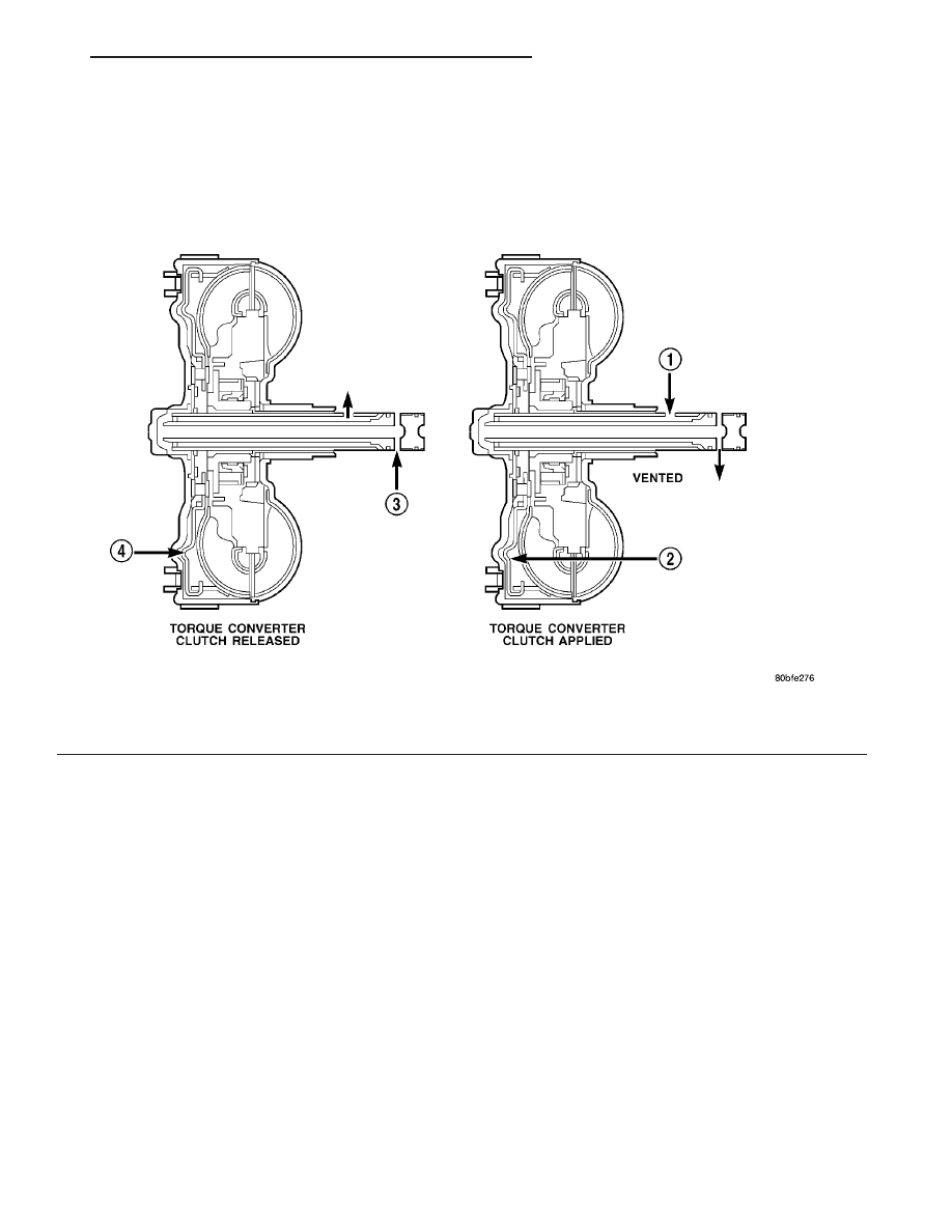
The converter impeller (Fig. 322) (driving member),

which is integral to the converter housing and bolted
to the engine drive plate, rotates at engine speed.
The converter turbine (driven member), which reacts
from fluid pressure generated by the impeller, rotates
and turns the transmission input shaft.

Fig. 322 Torque Converter Fluid Operation

1 - APPLY PRESSURE

3 - RELEASE PRESSURE

2 - THE PISTON MOVES SLIGHTLY FORWARD

4 - THE PISTON MOVES SLIGHTLY REARWARD

JR

40TE AUTOMATIC TRANSAXLE

21 - 177

TORQUE CONVERTER (Continued)

TURBINE

As the fluid that was put into motion by the impel-

ler blades strikes the blades of the turbine, some of
the energy and rotational force is transferred into the
turbine and the input shaft. This causes both of them
(turbine and input shaft) to rotate in a clockwise
direction following the impeller. As the fluid is leav-
ing the trailing edges of the turbine’s blades it con-
tinues in a “hindering” direction back toward the
impeller. If the fluid is not redirected before it strikes
the impeller, it will strike the impeller in such a
direction that it would tend to slow it down.

STATOR

Torque multiplication is achieved by locking the

stator’s over-running clutch to its shaft (Fig. 323).
Under stall conditions (the turbine is stationary), the
oil leaving the turbine blades strikes the face of the
stator blades and tries to rotate them in a counter-
clockwise direction. When this happens the over–run-
ning clutch of the stator locks and holds the stator
from rotating. With the stator locked, the oil strikes
the stator blades and is redirected into a “helping”
direction before it enters the impeller. This circula-
tion of oil from impeller to turbine, turbine to stator,
and stator to impeller, can produce a maximum
torque multiplication of about 2.4:1. As the turbine
begins to match the speed of the impeller, the fluid
that was hitting the stator in such as way as to
cause it to lock–up is no longer doing so. In this con-
dition of operation, the stator begins to free wheel
and the converter acts as a fluid coupling.

TORQUE CONVERTER CLUTCH (TCC)

In a standard torque converter, the impeller and

turbine are rotating at about the same speed and the
stator is freewheeling, providing no torque multipli-
cation. By applying the turbine’s piston to the front
cover’s friction material, a total converter engage-
ment can be obtained. The result of this engagement
is a direct 1:1 mechanical link between the engine
and the transmission.

The engagement and disengagement of the TCC

are automatic and controlled by the Powertrain Con-
trol Module (PCM). The engagement cannot be acti-
vated in the lower gears because it eliminates the
torque multiplication effect of the torque converter
necessary for acceleration. Inputs that determine
clutch engagement are: coolant temperature, vehicle
speed and throttle position. The torque converter
clutch is engaged by the clutch solenoid on the valve
body. The clutch will engage at approximately 56
km/h (35 mph) with light throttle, after the shift to
third gear.

REMOVAL

(1) Remove transmission and torque converter

from vehicle. (Refer to 21 - TRANSMISSION/TRANS-
AXLE/AUTOMATIC - 41TE - REMOVAL)

(2) Place a suitable drain pan under the converter

housing end of the transmission.

CAUTION: Verify that transmission is secure on the
lifting device or work surface, the center of gravity
of the transmission will shift when the torque con-
verter is removed creating an unstable condition.
The torque converter is a heavy unit. Use caution
when separating the torque converter from the
transmission.

(3) Pull the torque converter forward until the cen-

ter hub clears the oil pump seal.

(4) Separate the torque converter from the trans-

mission.

INSTALLATION

Check converter hub and drive notches for sharp

edges, burrs, scratches, or nicks. Polish the hub and
notches with 320/400 grit paper or crocus cloth if nec-
essary. The hub must be smooth to avoid damaging
the pump seal at installation.

(1) Lubricate converter hub and oil pump seal lip

with transmission fluid.

(2) Place torque converter in position on transmis-

sion.

CAUTION: Do not damage oil pump seal or bushing
while inserting torque converter into the front of the
transmission.

Fig. 323 Stator Operation

1 - DIRECTION STATOR WILL FREE WHEEL DUE TO OIL
PUSHING ON BACKSIDE OF VANES
2 - FRONT OF ENGINE
3 - INCREASED ANGLE AS OIL STRIKES VANES
4 - DIRECTION STATOR IS LOCKED UP DUE TO OIL PUSHING
AGAINST STATOR VANES

21 - 178

40TE AUTOMATIC TRANSAXLE

JR

TORQUE CONVERTER (Continued)

(3) Align torque converter to oil pump seal open-

ing.

(4) Insert torque converter hub into oil pump.
(5) While pushing torque converter inward, rotate

converter until converter is fully seated in the oil
pump gears.

(6) Check converter seating with a scale and

straightedge (Fig. 324). Surface of converter lugs
should be 1/2 in. to rear of straightedge when con-
verter is fully seated.

(7) If necessary, temporarily secure converter with

C-clamp attached to the converter housing.

(8) Install the transmission in the vehicle. (Refer

to 21 - TRANSMISSION/TRANSAXLE/AUTOMATIC
- 41TE - INSTALLATION)

(9) Fill the transmission with the recommended

fluid. (Refer to 21 - TRANSMISSION/TRANSAXLE/
AUTOMATIC - 41TE/FLUID - STANDARD PROCE-
DURE)

TRANSMISSION CONTROL
RELAY

DESCRIPTION

The transmission control relay (Fig. 325) is located

in the Power Distribution Center (PDC), which is
located on the left side of the engine compartment.

OPERATION

The relay is supplied fused B+ voltage, energized

by the PCM/TCM, and is used to supply power to the
solenoid pack when the transmission is in normal
operating mode. When the relay is “off”, no power is

supplied to the solenoid pack and the transmission is
in “limp-in” mode. After a controller reset (ignition
key turned to the “run” position or after cranking
engine), the PCM/TCM energizes the relay. Prior to
this, the PCM/TCM verifies that the contacts are
open by checking for no voltage at the switched bat-
tery terminals. After this is verified, the voltage at
the solenoid pack pressure switches is checked. After
the relay is energized, the PCM/TCM monitors the
terminals to verify that the voltage is greater than 3
volts.

TRANSMISSION RANGE
SENSOR

DESCRIPTION

The Transmission Range Sensor (TRS) is mounted

to the top of the valve body inside the transaxle and
can only be serviced by removing the valve body. The
electrical connector extends through the transaxle
case (Fig. 326).

The Transmission Range Sensor (TRS) has four

switch contacts that monitor shift lever position and
send the information to the PCM/TCM.

The TRS also has an integrated temperature sen-

sor (thermistor) that communicates transaxle tem-
perature to the TCM and PCM (Fig. 327).

Fig. 324 Checking Torque Converter Seating

1 - SCALE
2 - STRAIGHTEDGE

Fig. 325 Transmission Control Relay Location

1 - POWER DISTRIBUTION CENTER (PDC)
2 - TRANSMISSION CONTROL RELAY

JR

40TE AUTOMATIC TRANSAXLE

21 - 179

TORQUE CONVERTER (Continued)

OPERATION

The Transmission Range Sensor (TRS) (Fig. 326)

communicates shift lever position (SLP) to the PCM/
TCM as a combination of open and closed switches.
Each shift lever position has an assigned combina-
tion of switch states (open/closed) that the PCM/TCM
receives from four sense circuits. The PCM/TCM
interprets

this

information

and

determines

the

appropriate transaxle gear position and shift sched-
ule.

Since there are four switches, there are 16 possible

combinations of open and closed switches (codes).
Seven of these codes are related to gear position and
three are recognized as “between gear” codes. This
results in six codes which should never occur. These
are called “invalid” codes. An invalid code will result
in a DTC, and the PCM/TCM will then determine the
shift lever position based on pressure switch data.
This allows reasonably normal transmission opera-
tion with a TRS failure.

TRS SWITCH STATES

SLP

T42

T41

T3

T1

P

CL

CL

CL

OP

R

CL

OP

OP

OP

N

CL

CL

OP

CL

OD

OP

OP

OP

CL

3

OP

OP

CL

OP

L

CL

OP

CL

CL

TRANSMISSION TEMPERATURE SENSOR

The TRS has an integrated thermistor (Fig. 327)

that the PCM/TCM uses to monitor the transmis-
sion’s sump temperature. Since fluid temperature
can affect transmission shift quality and convertor
lock up, the PCM/TCM requires this information to
determine which shift schedule to operate in. The
PCM also monitors this temperature data so it can
energize the vehicle cooling fan(s) when a transmis-
sion “overheat” condition exists. If the thermistor cir-
cuit fails, the PCM/TCM will revert to calculated oil
temperature usage.

CALCULATED TEMPERATURE

A failure in the temperature sensor or circuit will

result in calculated temperature being substituted for
actual temperature. Calculated temperature is a pre-
dicted fluid temperature which is calculated from a
combination of inputs:

• Battery (ambient) temperature

• Engine coolant temperature

• In-gear run time since start-up

REMOVAL

(1) Remove valve body assembly from transaxle.

(Refer to 21 - TRANSMISSION/TRANSAXLE/AUTO-
MATIC - 41TE/VALVE BODY - REMOVAL)

(2) Remove transmission range sensor retaining

screw and remove sensor from valve body (Fig. 328).

(3) Remove TRS from manual shaft.

Fig. 326 Transmission Range Sensor (TRS)

Location

1 - TRANSMISSION RANGE SENSOR

Fig. 327 Transmission Temperature Sensor

1 - TRANSMISSION RANGE SENSOR
2 - TEMPERATURE SENSOR

21 - 180

40TE AUTOMATIC TRANSAXLE

JR

TRANSMISSION RANGE SENSOR (Continued)


Content   ..  602  603  604  605   ..