Chrysler Sebring, Stratus sedan, Sebring Convertible. Manual - part 601


  Index      Chrysler     Chrysler Sebring, Stratus sedan, Sebring Convertible - service repair manual 2001-2007 year


Search            


Content   ..  599  600  601  602   ..


Chrysler Sebring, Stratus sedan, Sebring Convertible. Manual - part 601


(13) Remove interlock cable from underside of

instrument panel.

INSTALLATION

CAUTION: When installing interlock cable assembly,
care must be taken not to bend exposed cable wire
and slug at shifter end of cable.

(1) Route interlock cable into lower dash panel and

towards console as removed.

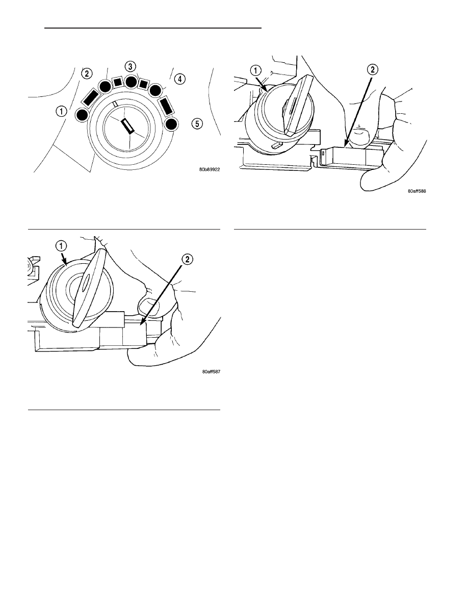
(2) Turn the ignition switch to the ON/RUN posi-

tion (Fig. 294).

(3) Install the interlock cable into the interlock

housing at the steering column (Fig. 296). Verify the
cable snaps into the housing.

(4) Install nylon cable retainer to lower column

mounting stud.

(5) Connect BTSI solenoid connector.
(6) Insert interlock cable core wire into interlock

adjustment lever groove. Make sure the interlock
cable slug is seated in the groove (Fig. 291).

(7) Insert interlock cable adjuster end into bracket

and snap into place (Fig. 291).

NOTE: The Interlock Cable MUST be adjusted.
(Refer to 21 - TRANSMISSION/TRANSAXLE/AUTO-
MATIC - 41TE/SHIFT INTERLOCK CABLE - ADJUST-
MENTS)

(8) Install center console assembly (Fig. 289).
(9) Install gearshift bezel (Fig. 287).
(10) Install the gearshift knob and tighten set

screw (Fig. 287) to 2 N·m (20 in.lbs.).

(11) Tilt wheel to full down position and install

upper steering column shroud.

(12) Install steering column lower shroud (Fig.

293).

(13) Install lower knee bolster screws and knee

bolster.

(14) Install fuse panel cover (Fig. 292).
(15) Connect the battery negative cable.

ADJUSTMENTS

BRAKE/TRANSMISSION SHIFT INTERLOCK
CABLE VERIFICATION AND ADJUSTMENT

VERIFICATION

The following chart describes the normal operation

of the Brake Transmission Shift Interlock (BTSI) sys-
tem. If the “expected response” differs from the vehi-

Fig. 294 Ignition Key/Switch Positions

1 - ACC
2 - LOCK
3 - OFF
4 - ON/RUN
5 - START

Fig. 295 Interlock Cable and Connector

1 - IGNITION LOCK CYLINDER
2 - INTERLOCK CABLE

Fig. 296 Interlock Cable At Housing

1 - IGNITION LOCK CYLINDER
2 - INTERLOCK CABLE

JR

40TE AUTOMATIC TRANSAXLE

21 - 165

SHIFT INTERLOCK CABLE (Continued)

cle’s response, then system repair and/or adjustment
is necessary. Refer to the following chart that
expected shifter response, depending on ignition key/
switch (Fig. 297) and brake pedal positions.

ACTION

EXPECTED RESPONSE

1. Turn key to the

9

OFF

9

position.

1. Shifter CAN be shifted
out of park.

2. Turn key to the

9

ON/RUN

9

position.

2. Shifter CANNOT be
shifted out of park.

3. Turn key to the

9

ON/RUN

9

position and

depress the brake pedal.

3. Shifter CAN be shifted
out of park.

4. Leave shifter in any
gear and try to return key
to the

9

LOCK

9

or

9

ACC

9

position.

4. Key cannot be
returned to the

9

LOCK

9

or

9

ACC

9

position.

5. Return shifter to

9

PARK

9

and try to remove

the key.

5. Key can be removed
(after returning to

9

LOCK

9

position).

6. With the key removed,
try to shift out of

9

PARK

9

.

6. Shifter cannot be
shifted out of

9

PARK

9

.

NOTE: Any failure to meet these expected
responses requires system adjustment or repair.

ADJUSTMENT

(1) Disconnect and isolate, the battery negative

cable.

(2) Remove the gearshift knob set screw and knob

(Fig. 298).

(3) Remove the gearshift bezel to gain access to

the interlock cable adjuster lock (Fig. 299).

(4) Re-install the gearshift knob set screw and

knob (Fig. 298).

(5) Place the shift lever in PARK. Move the Igni-

tion key to the LOCK position (Fig. 297) and remove
the key.

Fig. 297 Ignition Key/Switch Positions

1 - ACC
2 - LOCK
3 - OFF
4 - ON/RUN
5 - START

Fig. 298 Gearshift Knob

1 - GEARSHIFT KNOB
2 - SET SCREW
3 - GEARSHIFT MECHANISM

Fig. 299 Gearshift Bezel

1 - CENTER CONSOLE ASSEMBLY
2 - GEARSHIFT BEZEL
3 - LAMP CONNECTOR

21 - 166

40TE AUTOMATIC TRANSAXLE

JR

SHIFT INTERLOCK CABLE (Continued)

(6) If the interlock cable is being replaced, remove

the lock pin (Fig. 300). This will allow the cable to
“self adjust” to the correct position. Tighten the lock-
ing clip by pushing it down (Fig. 301).

(7) If the interlock cable is not being replaced, the

lock pin will not exist. Pull outward on cable locking
clip to allow cable to self adjust. Press clip down to
lock in place (Fig. 301).

(8) Verify Brake/Transmission Shift Interlock sys-

tem operation. Refer to operation chart in “Verifica-
tion.”

(9) Install the gearshift bezel (Fig. 299).
(10) Install the gearshift knob and tighten set

screw (Fig. 298) to 2 N·m (20 in. lbs.).

(11) Connect the battery negative cable.

SHIFT INTERLOCK
MECHANISM

REMOVAL

(1) Remove steering column upper and lower

shrouds.

(2) Grasp the interlock cable and connector firmly.

Remove the interlock cable.

(3) Remove the two interlock mechanism to steer-

ing column attaching screws (Fig. 302). Remove the
interlock mechanism.

INSTALLATION

(1) Position the interlock housing at steering col-

umn. Install the two interlock mechanism to steering
column attaching screws (Fig. 302). Torque screws to
3 N·m (21 in. lbs.).

(2) Snap the interlock cable into the housing.
(3) Install the lower column covers, shrouds and

knee bolster.

Fig. 300 Interlock Cable Locking Pin

1 - SHIFT MECHANISM
2 - LOCKING PIN
3 - INTERLOCK CABLE

Fig. 301 Locking Clip

1 - LOCKING CLIP

Fig. 302 Interlock Mechanism

1 - MOUNTING SCREW
2 - INTERLOCK MECHANISM

JR

40TE AUTOMATIC TRANSAXLE

21 - 167

SHIFT INTERLOCK CABLE (Continued)

SOLENOID/PRESSURE
SWITCH ASSY

DESCRIPTION

The Solenoid/Pressure Switch Assembly (Fig. 303)

is external to the transaxle and mounted to the
transaxle case. The assembly consists of four sole-
noids that control hydraulic pressure to the LR/CC,
2/4, OD, and UD friction elements. The reverse
clutch is controlled by line pressure from the manual
valve in the valve body. The solenoids are contained
within the Solenoid/Pressure Switch Assembly, and
can only be serviced by replacing the assembly.

The solenoid assembly also contains pressure

switches that monitor and send hydraulic circuit
information to the PCM/TCM. Likewise, the pressure
switches can only be service by replacing the assem-
bly.

OPERATION

SOLENOIDS

The solenoids receive electrical power from the

Transmission Control Relay through a single wire.
The PCM/TCM energizes or operates the solenoids
individually by grounding the return wire of the sole-
noid needed. When a solenoid is energized, the sole-
noid valve shifts, and a fluid passage is opened or
closed (vented or applied), depending on its default
operating state. The result is an apply or release of a
frictional element.

The 2/4 and UD solenoids are normally applied,

which by design allow fluid to pass through in their
relaxed or “off” state. This allows transaxle limp-in
(P,R,N,2) in the event of an electrical failure.

The continuity of the solenoids and circuits are

periodically tested. Each solenoid is turned on or off
depending on its current state. An inductive spike
should be detected by the PCM/TCM during this test.
It no spike is detected, the circuit is tested again to
verify the failure. In addition to the periodic testing,
the solenoid circuits are tested if a speed ratio or
pressure switch error occurs.

PRESSURE SWITCHES

The PCM/TCM relies on three pressure switches to

monitor fluid pressure in the L/R, 2/4, and OD
hydraulic circuits. The primary purpose of these
switches is to help the PCM/TCM detect when clutch
circuit hydraulic failures occur. The range for the
pressure switch closing and opening points is 11-23
psi. Typically the switch opening point will be
approximately one psi lower than the closing point.
For example, a switch may close at 18 psi and open
at 17 psi. The switches are continuously monitored
by the PCM/TCM for the correct states (open or
closed) in each gear as shown in the following chart:

PRESSURE SWITCH STATES

GEAR

L/R

2/4

OD

R

OP

OP

OP

P/N

CL

OP

OP

1st

CL

OP

OP

2nd

OP

CL

OP

D

OP

OP

CL

OD

OP

CL

CL

OP = OPEN

CL = CLOSED

A Diagnostic Trouble Code (DTC) will set if the

PCM/TCM senses any switch open or closed at the
wrong time in a given gear.

The PCM/TCM also tests the 2/4 and OD pressure

switches when they are normally off (OD and 2/4 are
tested in 1st gear, OD in 2nd gear, and 2/4 in 3rd
gear). The test simply verifies that they are opera-
tional, by looking for a closed state when the corre-
sponding element is applied. Immediately after a
shift into 1st, 2nd, or 3rd gear with the engine speed
above 1000 rpm, the PCM/TCM momentarily turns
on element pressure to the 2/4 and/or OD clutch cir-
cuits to identify that the appropriate switch has
closed. If it doesn’t close, it is tested again. If the
switch fails to close the second time, the appropriate
Diagnostic Trouble Code (DTC) will set.

Fig. 303 Solenoid/Pressure Switch Assembly

1 - SOLENOID AND PRESSURE SWITCH ASSEMBLY

21 - 168

40TE AUTOMATIC TRANSAXLE

JR


Content   ..  599  600  601  602   ..