Chrysler Sebring, Stratus sedan, Sebring Convertible. Manual - part 588


  Index      Chrysler     Chrysler Sebring, Stratus sedan, Sebring Convertible - service repair manual 2001-2007 year


Search            


Content   ..  586  587  588  589   ..


Chrysler Sebring, Stratus sedan, Sebring Convertible. Manual - part 588


OPERATION

The function of an accumulator is to cushion the

application of a frictional clutch element. When pres-
surized fluid is applied to a clutch circuit, the appli-
cation force is dampened by fluid collecting in the
respective accumulator chamber against the piston
and spring(s). The intended result is a smooth, firm
clutch application.

AUTOSTICK SWITCH

DESCRIPTION

Autostick is a driver–interactive transaxle feature

that offers manual gear shifting capability of an
automatic transaxle.

OPERATION

When the shifter is moved into the Autostick posi-

tion, the transaxle remains in whatever gear it was

using before Autostick was activated. Moving the
shifter to the left (towards the driver) causes a down-
shift and moving to the right (towards the passenger)
causes an upshift. The instrument cluster will illumi-
nate the selected gear. The vehicle can be launched
in 1st, 2nd, or 3rd gear while in the Autostick mode.
The speed control is operable in 3rd and 4th gear
Autostick mode. Speed control will be deactivated if
the transaxle is shifted to 2nd gear. Shifting into OD
position cancels the Autostick mode, and the trans-
axle resumes the OD shift schedule.

AUTOMATIC OVERRIDES

For safety, durability, and driveability, some shifts

are executed automatically or prevented.

AUTOMATIC SHIFTS WILL OCCUR UNDER THE FOLLOWING CONDITIONS

TYPE OF SHIFT

APPROXIMATE SPEED

4-3 coast downshift

13 mph

3-2 coast downshift

9 mph

2-1 coast downshift

5 mph

1-2 upshift

6300 engine rpm

2-3 upshift

6300 engine rpm

4-3 kickdown shift

13-47 mph w/sufficient throttle

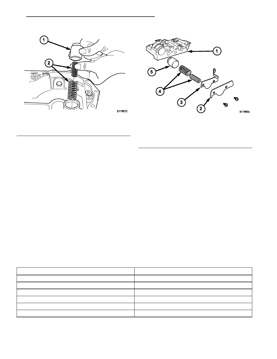
Fig. 154 Low/Reverse Accumulator

1 - PISTON
2 - RETURN SPRINGS

Fig. 155 2/4 Accumulator Assembly

1 - VALVE BODY
2 - RETAINER PLATE
3 - DETENT SPRING
4 - RETURN SPRINGS
5 - PISTON

JR

40TE AUTOMATIC TRANSAXLE

21 - 113

ACCUMULATOR (Continued)

MANUAL SHIFTS ARE NOT PERMITTED UNDER THE FOLLOWING CONDITIONS

TYPE OF SHIFT

APPROXIMATE SHIFT POINT

3-4 upshift

Below 15 mph

3-2 downshift

Above 74 mph @ closed throttle or 70 mph otherwise

2-1 downshift

Above 41 mph @ closed throttle or 38 mph otherwise

DRIVING CLUTCHES

DESCRIPTION

Three hydraulically applied input clutches are used

to drive planetary components. The underdrive, over-
drive, and reverse clutches are considered input
clutches and are contained within the input clutch
assembly (Fig. 156). The input clutch assembly also
contains:

• Input shaft

• Input hub

• Clutch retainer

• Underdrive piston

• Overdrive/reverse piston

• Overdrive hub

• Underdrive hub

OPERATION

The three input clutches are responsible for driving

different components of the planetary geartrain.

NOTE: Refer to the “Elements In Use” chart in Diag-
nosis and Testing for a collective view of which
clutch elements are applied at each position of the
selector lever.

UNDERDRIVE CLUTCH

The underdrive clutch is hydraulically applied in

first, second, and third (direct) gears by pressurized
fluid against the underdrive piston. When the under-
drive clutch is applied, the underdrive hub drives the
rear sun gear.

OVERDRIVE CLUTCH

The overdrive clutch is hydraulically applied in

third (direct) and overdrive gears by pressurized fluid
against the overdrive/reverse piston. When the over-
drive clutch is applied, the overdrive hub drives the
front planet carrier.

REVERSE CLUTCH

The reverse clutch is hydraulically applied in

reverse gear only by pressurized fluid against the
overdrive/reverse piston. When the reverse clutch is
applied, the front sun gear assembly is driven.

Fig. 156 Input Clutch Assembly

1 - INPUT SHAFT
2 - UNDERDRIVE CLUTCH
3 - OVERDRIVE CLUTCH
4 - REVERSE CLUTCH
5 - OVERDRIVE SHAFT
6 - UNDERDRIVE SHAFT

21 - 114

40TE AUTOMATIC TRANSAXLE

JR

AUTOSTICK SWITCH (Continued)

FINAL DRIVE

DESCRIPTION

The 4XTE differential is a conventional open

design. It consists of a ring gear and a differential
case. The differential case consists of pinion and side
gears, and a pinion shaft. The differential case is
supported in the transaxle by tapered roller bearings
(Fig. 157).

OPERATION

The differential assembly is driven by the transfer

shaft by way of the differential ring gear. The ring
gear drives the differential case, and the case drives
the driveshafts through the differential gears. The
differential pinion and side gears are supported in
the case by thrust washers and a pinion shaft. Dif-
ferential pinion and side gears make it possible for
front tires to rotate at different speeds while corner-
ing.

DISASSEMBLY

NOTE: The transfer shaft should be removed for dif-
ferential repair and bearing turning torque check-
ing.

(1) Remove the differential cover and bolts (Fig.

158) (Fig. 159).

Fig. 157 Differential Assembly

1 - DIFFERENTIAL CASE
2 - RING GEAR
3 - TRANSFER SHAFT
4 - PINION GEAR
5 - PINION SHAFT
6 - SIDE GEAR

Fig. 158 Differential Cover Bolts

1 - DIFFERENTIAL COVER BOLTS
2 - DIFFERENTIAL COVER

Fig. 159 Remove Differential Cover

1 - DIFFERENTIAL ASSEMBLY
2 - DIFFERENTIAL COVER

JR

40TE AUTOMATIC TRANSAXLE

21 - 115

(2) Remove the differential bearing retainer and

bolts (Fig. 160) (Fig. 161).

(3) Using a plastic hammer, remove extension

housing/adapter plate on the right side of the trans-
axle.

WARNING: HOLD ONTO DIFFERENTIAL ASSEMBLY
TO PREVENT IT FROM ROLLING OUT OF HOUSING.

(4) Remove differential assembly.
(5) Set up dial indicator set C-3339 and tool

C-4996 as shown in (Fig. 162) (Fig. 163) to measure
side gear end play. Side gear end play must be
within 0.001-0.013 in.

Fig. 160 Differential Retainer Bolts

1 - DIFFERENTIAL RETAINER BOLTS

Fig. 161 Remove Bearing Retainer

1 - DIFFERENTIAL BEARING RETAINER
2 - TOOL L-4435

Fig. 162 Checking Side Gear End Play (Extension

Housing Side)

1 - SPECIAL TOOL C-4996 (NOTE POSITION)
2 - DIAL INDICATOR SET
3 - DIFFERENTIAL ASSEMBLY
4 - SIDE GEAR

Fig. 163 Checking Side Gear End Play (Ring Gear

Side)

1 - SPECIAL TOOL C-4996 (NOTE POSITION)
2 - DIAL INDICATOR SET
3 - DIFFERENTIAL ASSEMBLY

21 - 116

40TE AUTOMATIC TRANSAXLE

JR

FINAL DRIVE (Continued)


Content   ..  586  587  588  589   ..