Chrysler Sebring, Stratus sedan, Sebring Convertible. Manual - part 582


  Index      Chrysler     Chrysler Sebring, Stratus sedan, Sebring Convertible - service repair manual 2001-2007 year


Search            


Content   ..  580  581  582  583   ..


Chrysler Sebring, Stratus sedan, Sebring Convertible. Manual - part 582


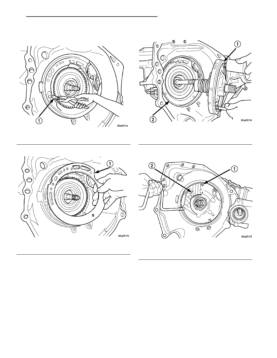
(55) Install cooler bypass valve with o-ring end

towards rear of case (Fig. 139).

(56) Install oil pump gasket (Fig. 140).

(57) Install oil pump assembly (Fig. 141).

(58) Install oil pump-to-case bolts and torque to 27

N·m (20 ft. lbs.) (Fig. 142).

Fig. 139 Install Cooler Bypass Valve

1 - COOLER BYPASS VALVE

Fig. 140 Install Oil Pump Gasket

1 - PUMP GASKET

Fig. 141 Install Oil Pump

1 - OIL PUMP
2 - GASKET

Fig. 142 Install Pump-to-Case Bolts

1 - PUMP ATTACHING BOLTS
2 - PUMP HOUSING

JR

40TE AUTOMATIC TRANSAXLE

21 - 89

40TE AUTOMATIC TRANSAXLE (Continued)

(59) Install low/reverse accumulator (Fig. 143).

(60) Install low/reverse accumulator plug (Fig.

144).

(61) Install low/reverse accumulator snap ring

(Fig. 145).

NOTE: Depending on engine application, some
accumulators will have two springs, and others will
have one spring. The springs are color-coded for
application and year.

(62) Install underdrive and overdrive accumulators

and springs (Fig. 146).

Fig. 143 Low/Reverse Accumulator

1 - PISTON
2 - RETURN SPRINGS

Fig. 144 Install Low/Reverse Accumulator Plug

1 - ADJUSTABLE PLIERS
2 - PLUG

Fig. 145 Install Low/Reverse Accumulator Snap

Ring

1 - SNAP RING
2 - PLUG

Fig. 146 Underdrive and Overdrive Accumulators

1 - OVERDRIVE PISTON AND SPRING
2 - UNDERDRIVE PISTON AND SPRING

21 - 90

40TE AUTOMATIC TRANSAXLE

JR

40TE AUTOMATIC TRANSAXLE (Continued)

(63) Install valve body to transaxle (Fig. 147).

Rotate manual valve shaft fully clockwise to ease
installation. Make sure park rod rollers are posi-
tioned within park guide bracket.

(64) Install and torque valve body-to-case bolts to

12 N·m (105 in. lbs.) (Fig. 148).

(65) Install oil filter and new o-ring (Fig. 149).

(66) Apply an 1/8” bead of Mopar

t ATF RTV (MS-

GF41) to oil pan and immediately install to case (Fig.
150).

(67) Install oil pan-to-case bolts and torque to 19

N·m (165 in. lbs.).

Fig. 147 Valve Body Removal/Installation

1 - VALVE BODY

Fig. 148 Install Valve Body-to-Case Bolts

1 - VALVE BODY ATTACHING BOLTS (18)
2 - VALVE BODY

Fig. 149 Install Oil Filter and O-Ring

1 - OIL FILTER
2 - O-RING

Fig. 150 Install Oil Pan

1 - OIL PAN
2 - 1/8 INCH BEAD OF MOPAR

T

ATF RTV (MS-GF41)

3 - OIL FILTER

JR

40TE AUTOMATIC TRANSAXLE

21 - 91

40TE AUTOMATIC TRANSAXLE (Continued)

(68) Install solenoid/pressure switch assembly and

gasket to case (Fig. 151).

(69) Install and tighten solenoid/pressure switch

assembly-to-transaxle case bolts to 12 N·m (110 in.
lbs.) (Fig. 152).

(70) Install and torque input and output speed

sensors to case to 27 N·m (20 ft. lbs.).

INSTALLATION

(1) Install transaxle to engine. Install and torque

transaxle-to-engine bolts to 95 N·m (70 ft. lbs.).

(2) Install upper mount to transaxle.
(3) Raise engine/transaxle assembly into position

and install thru bolt. Torque thru bolt to 70 N·m (55
ft. lbs.).

(4) Remove transmission jack and screw jack.
(5) Install torque converter bolts.
(6) Install torque converter dust shield.
(7) Install starter motor assembly and lower bolt.
(8) Install front mount/bracket assembly.
(9) Install rear mount/bracket assembly.
(10) Install halfshafts. (Refer to 3 - DIFFEREN-

TIAL & DRIVELINE/HALF SHAFT - INSTALLA-
TION)

(11) Lower vehicle.
(12) Install starter upper bracket-to-block bolt.
(13) Connect oxygen sensor harness connector.
(14) Install

throttle

body

support

bracket

(if

equipped).

(15) Connect crankshaft position sensor connector

(if equipped).

(16) Connect gearshift cable to manual valve lever.
(17) Connect output speed sensor connector.
(18) Connect input speed sensor connector.
(19) Connect transmission range sensor connector.
(20) Connect solenoid/pressure switch assembly

connector.

(21) Connect oil cooler lines to the transaxle. An

audible ’click’ should be heard. Verify connection by
pulling outward.

(22) Install dipstick tube.
(23) Install air cleaner assembly.
(24) Connect battery negative cable.

Fig. 151 Solenoid/Pressure Switch Assembly and

Gasket

1 - SOLENOID/PRESSURE SWITCH ASSEMBLY
2 - GASKET

Fig. 152 Attaching Bolts

1 - BOLTS
2 - SOLENOID AND PRESSURE SWITCH ASSEMBLY

21 - 92

40TE AUTOMATIC TRANSAXLE

JR

40TE AUTOMATIC TRANSAXLE (Continued)


Content   ..  580  581  582  583   ..