Chrysler Sebring, Stratus sedan, Sebring Convertible. Manual - part 567


  Index      Chrysler     Chrysler Sebring, Stratus sedan, Sebring Convertible - service repair manual 2001-2007 year


Search            


Content   ..  565  566  567  568   ..


Chrysler Sebring, Stratus sedan, Sebring Convertible. Manual - part 567


GEAR SHIFT CABLE

REMOVAL

(1) Disconnect battery negative cable.
(2) Remove gearshift knob/boot assembly. Lift boot

off of console and disengage knob retainers to free.

(3) Remove center console assembly (Fig. 79).

(4) Disconnect crossover and selector cables from

shift mechanism.

(5) Remove crossover and selector cable retaining

clips (Fig. 80) from shift mechanism and disconnect
cables.

(6) Remove air cleaner assembly.
(7) Disconnect crossover and selector cables from

transaxle (Fig. 81).

(8) Remove retainer clips and disengage cables

from bracket (Fig. 81).

(9) Raise vehicle on hoist.
(10) Remove cable grommet from floor pan.
(11) Pull cables forward and remove from under

vehicle.

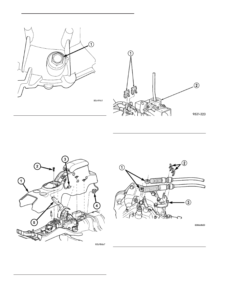
Fig. 78 Drain Plug Location

1 - DRAIN PLUG

Fig. 79 Center Console Assembly—Typical

1 - CENTER CONSOLE
2 - SCREW
3 - IF EQUIPPED
4 - IF EQUIPPED
5 - PARK BRAKE HANDLE

Fig. 80 Cable Retaining Clips

1 - CABLE CLIPS
2 - SHIFTER

Fig. 81 Shift Cables at Transaxle

1 - SHIFT CABLES
2 - CLIPS
3 - BRACKET

JR

T350 MANUAL TRANSAXLE

21 - 29

FLUID (Continued)

INSTALLATION

(1) Install gearshift cable assembly into engine

compartment from under vehicle.

(2) Feed cable assembly through hole in floor pan

and secure grommet to floor pan.

(3) Lower vehicle.
(4) Install gearshift cables to mounting bracket

(Fig. 81). Secure with new clips.

(5) Connect gearshift cables to transaxle crossover

and selector levers (Fig. 81).

(6) Install air cleaner assembly.
(7) Connect crossover and selector cables to mech-

anism and secure with clips (Fig. 80).

NOTE: Only the crossover cable is adjustable. The
selector cable does not have any adjustment capa-
bilities.

(8) Adjust crossover cable as follows:

(a) Loosen adjusting screw on crossover cable at

shifter (Fig. 82).

(b) The

gearshift

mechanism

and

transaxle

crossover lever are spring-loaded and self-center-
ing. Alignment pins used in the past are not
required anymore. Allow gearshift mechanism and
transaxle crossover lever to relax in their neutral
positions. To ensure the gearshift lever is in the
proper position, place the shifter in 3rd or 4th gear
if necessary. Torque adjustment screw to 8 N·m (70
in. lbs.). Care must be taken to avoid moving the
shift mechanism off-center during screw tighten-
ing.

(c) Perform functional check by shifting trans-

axle into all gears.

(9) Install center console assembly (Fig. 79).
(10) Install gearshift knob/boot assembly. Ensure

knob retaining tabs are secured to shift lever. Snap
boot to console at retainer locations.

GEAR SHIFT MECHANISM

REMOVAL

(1) Disconnect battery negative cable.
(2) Remove gearshift knob/boot assembly.
(3) Remove center console assembly (Fig. 83).

(4) Disconnect crossover cable from mechanism.
(5) Disconnect selector cable from mechanism.
(6) Remove crossover and selector cable retaining

clips (Fig. 84) from mechanism and disconnect cables.

(7) Remove shift mechanism-to-floor pan bolts and

remove mechanism (Fig. 85).

Fig. 82 Crossover and Selector Cables at Shift

Mechanism

1 - CABLE CLIPS
2 - SHIFTER
3 - ADJUSTMENT SCREW

Fig. 83 Center Console Assembly—Typical

1 - CENTER CONSOLE
2 - SCREW
3 - IF EQUIPPED
4 - IF EQUIPPED
5 - PARK BRAKE HANDLE

21 - 30

T350 MANUAL TRANSAXLE

JR

GEAR SHIFT CABLE (Continued)

INSTALLATION

(1) Install gear shift mechanism to floor pan (Fig.

85). Install and torque four (4) nuts to 25 N·m (18 ft.
lbs.).

(2) Install crossover and selector cables into posi-

tion. Secure with retaining clips (Fig. 86).

NOTE: Only the crossover cable is adjustable. The
selector cable does not have any adjustment capa-
bilities.

(3) Adjust crossover cable as follows:

(a) Loosen adjusting screw on crossover cable at

shifter (Fig. 86).

(b) The

gearshift

mechanism

and

transaxle

crossover lever are spring-loaded and self-center-
ing. Alignment pins used in the past are not
required anymore. Allow gearshift mechanism and
transaxle crossover lever to relax in their neutral
positions. To ensure the gearshift lever is in the
proper position, place the shifter in 3rd or 4th gear
if necessary. Torque adjustment screw to 8 N·m (70
in. lbs.). Care must be taken to avoid moving the
shift mechanism off-center during screw tighten-
ing.

(c) Perform functional check by shifting trans-

axle into all gears.
(4) Install center console assembly (Fig. 83).
(5) Install gearshift knob/boot assembly. Ensure

knob retaining tabs are secured to shift lever. Snap
boot to console at retainer locations.

INPUT BEARING AND SLEEVE

REMOVAL

The input bearing is a one–piece bearing and

sleeve unit (Fig. 87). The sleeve is the slide point for
the clutch–release bearing and lever.

(1) Install tool #6342 over input bearing on the

gear case side of the transaxle clutch housing.

(2) Press the input bearing out of the housing (Fig.

88).

INSTALLATION

(1) Apply coating of Loctite

t sealant on bearing

outer diameter. Position sleeve and bearing assembly
at input bearing bore.

Fig. 84 Cable Retaining Clips

1 - CABLE CLIPS
2 - SHIFTER

Fig. 85 Gearshift Mechanism

1 - GEARSHIFT MECHANISM
2 - NUT (5)
3 - GEARSHIFT CABLES

Fig. 86 Crossover and Selector Cables at Shift

Mechanism

1 - CABLE CLIPS
2 - SHIFTER
3 - ADJUSTMENT SCREW

JR

T350 MANUAL TRANSAXLE

21 - 31

GEAR SHIFT MECHANISM (Continued)

(2) Install tool #C-4680-1 over input bearing (Fig.

89).

(3) Using a suitable spacer tool and shop press,

install input bearing into bore until it is fully seated
(Fig. 90).

INPUT SHAFT

DISASSEMBLY

Before disassembly of the input shaft, it is neces-

sary to check the synchronizer stop ring gap. Use a
feeler gauge to measure the gaps between the stop
rings and the speed gears. The correct gaps are listed
below:

• 1st - 0.522-2.208 mm (0.021-0.087 in)

• 2nd - 0.522-2.208 mm (0.021-0.087 in)

• 3rd - 0.73-1.53 mm (0.029-0.060 in)

• 4th - 0.77-1.57 mm (0.030-0.062 in).

• 5th - 0.73-1.53 mm (0.029-0.060 in)

• Reverse Brake—0.505-1.74 mm (0.020-0.068 in.)
The reverse brake measurement is taken between

the stop ring and case.

Fig. 87 Input Bearing And Sleeve

1 - DIFFERENTIAL BEARING
2 - OUTPUT BEARING
3 - INPUT BEARING
4 - BEARING RETAINER

Fig. 88 Input Bearing Removal

1 - SPECIAL TOOL 6342
2 - BELLHOUSING HALF
3 - INPUT BEARING AND SLEEVE

Fig. 89 Input Bearing Tool

1 - SPECIAL TOOL C-4680-1
2 - SPACER
3 - BELLHOUSING HALF

Fig. 90 Input Bearing Installed

1 - SLEEVE AND BEARING ASSEMBLY

21 - 32

T350 MANUAL TRANSAXLE

JR

INPUT BEARING AND SLEEVE (Continued)


Content   ..  565  566  567  568   ..