Chrysler Sebring, Stratus sedan, Sebring Convertible. Manual - part 563


  Index      Chrysler     Chrysler Sebring, Stratus sedan, Sebring Convertible - service repair manual 2001-2007 year


Search            


Content   ..  561  562  563  564   ..


Chrysler Sebring, Stratus sedan, Sebring Convertible. Manual - part 563


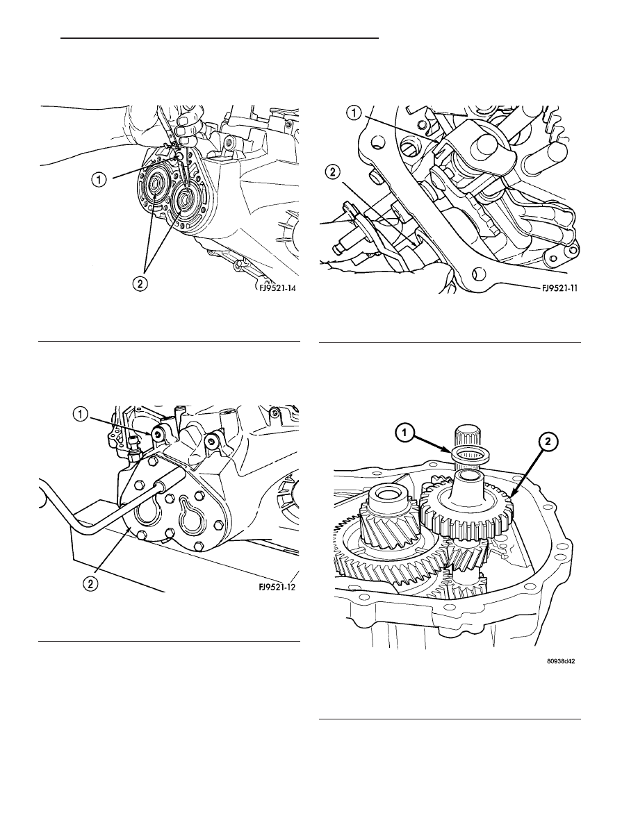
(9) Install shaft snap rings at input and output

bearings (Fig. 38).

(10) Apply Mopar

t RTV sealant to end–cover outer

edge and around bolt holes. Install end–cover onto
gear case. Tighten end cover bolts to 29 N·m (21 ft.
lbs.) torque (Fig. 39).

(11) Remove gear case from bench fixture.
(12) Install gear case in a holding fixture with end

cover facing down.

(13) Turn selector shaft into slot on blocker assem-

bly (Fig. 40).

(14) Push selector shaft spacer clip onto selector

shaft. Install shift levers.

(15) Install reverse idler gear and spacer as shown

in (Fig. 41).

Fig. 38 Snap Rings Retaining Bearings

1 - SNAP RING PLIERS
2 - SNAP RINGS

Fig. 39 Transaxle End Cover

1 - TRANSAXLE CASE
2 - END COVER

Fig. 40 Selector Shaft

1 - SHIFT ASSEMBLY
2 - SELECTOR SHAFT

Fig. 41 Reverse Idler Gear and Spacer

1 - SPACER
2 - REVERSE IDLER GEAR

JR

T350 MANUAL TRANSAXLE

21 - 13

T350 MANUAL TRANSAXLE (Continued)

(16) Install reverse idler shaft (Fig. 42).

(17) Install bolt into shaft and tighten to 26 N·m

(19 ft. lbs.) torque (Fig. 43).

(18) Install reverse fork bracket and reverse lock-

out. Tighten screws to 11 N·m (96 in. lbs.) torque
(Fig. 44) (Fig. 45).

Fig. 42 Reverse Idler Shaft Installation

1 - REVERSE IDLER SHAFT
2 - SPACER

Fig. 43 Reverse Idler Shaft Bolt

1 - CASE
2 - REVERSE IDLER SHAFT
3 - REVERSE IDLER SHAFT BOLT

Fig. 44 Reverse Fork Bracket

1 - REVERSE FORK BRACKET
2 - REVERSE CAM BLOCKOUT
3 - SHIFT BLOCKER ASSEMBLY

Fig. 45 Reverse Fork Screws

1 - SCREWS (2)
2 - REVERSE FORK BRACKET

21 - 14

T350 MANUAL TRANSAXLE

JR

T350 MANUAL TRANSAXLE (Continued)

(19) Install differential into gear case (Fig. 46).

BEARING ADJUSTMENT PROCEDURE

(1) Use extreme care when removing and install-

ing bearing cups and cones. Use only an arbor press
for installation, as a hammer may not properly align
the bearing cup or cone. Burrs or nicks on the bear-
ing seat gives a false end–play reading while gauging
for proper shims. Improperly seated bearing cups and
cones are subject to low–mileage failure.

(2) Bearing cups and cones should be replaced if

they show signs of pitting or heat distress. If distress
is seen on either the cup or bearing rollers, both cup
and cone must be replaced.

(3) Bearing preload and drag torque specifications

must be maintained to avoid premature bearing fail-
ures. Used (original) bearings may lose up to 50% of
the original drag torque after break–in. All bearing
adjustments must be made with no other component
interference or gear intermesh.

(4) Replace bearings as a pair: If one differential

bearing is defective, replace both differential bear-
ings, if one input shaft bearing is defective, replace
both input shaft bearings.

(5) Bearing cones must not be reused if removed.
(6) Turning–torque readings should be obtained

while smoothly rotating in either direction.

DIFFERENTIAL BEARING PRELOAD ADJUSTMENT

NOTE: True bearing turning–torque readings can be
obtained only with the geartrain removed from the
case.

(1) Remove bearing cup and existing shim from

clutch bellhousing case.

(2) Press in new bearing cup into bellhousing case

(or use a cup that has been ground down on the
outer edge for ease of measurement).

(3) Press in new bearing cup into gear case side.
(4) Oil differential bearings with transmission

fluid. Install differential assembly in transaxle gear
case. Install clutch bellhousing over gear case. Install
and torque case bolts to 29 N·m (21 ft. lbs.).

(5) Position

transaxle

with

bellhousing

facing

down on workbench with C-clamps. Position dial
indicator.

NOTE: Position of dial indicator in (Fig. 47) is for
illustrative purposes only. The dial indicator should
be parallel to T-Handle to obtain the most accurate
reading.

(6) Apply a medium load to differential with Tool

C-4995 and a T-handle, in the downward direction.
Roll differential assembly back and forth a number of
times. This will settle the bearings. Zero the dial
indicator. To obtain end play readings, apply a
medium load in an upward direction while rolling
differential assembly back and forth (Fig. 47). Record
end play.

Fig. 46 Differential Removal/Installation

1 - INPUT SHAFT
2 - OUTPUT SHAFT
3 - DIFFERENTIAL ASSEMBLY
4 - GEARTRAIN HOUSING

Fig. 47 Checking Differential Bearing End Play To

Determine Shim Thickness

1 - T-HANDLE
2 - DIAL INDICATOR SET
3 - SPECIAL TOOL C-4995

JR

T350 MANUAL TRANSAXLE

21 - 15

T350 MANUAL TRANSAXLE (Continued)

(7) The shim required for proper bearing preload is

the total of end play, plus (constant) preload of
0.18mm (0.007 in.). 
Never combine shims to obtain
the required preload.

(8) Remove case bolts. Remove clutch bellhousing

differential bearing cup. Install shim(s) selected in
Step 7. Then press the bearing cup into clutch bell-
housing.

(9) Install clutch bellhousing. Install and torque

case bolts to 26 N·m (19 ft. lbs.).

(10) Using Special Tool C-4995 and an inch-pound

torque wrench, check turning torque of the differen-
tial assembly (Fig. 48). The turning torque should
be 6 to 12 in. lbs. If the turning torque is too
high, install a 0.05mm (0.002 inch) thinner shim.
If the turning torque is too low, install a
0.05mm (0.002 inch) thicker shim.

(11) Recheck turning torque. Repeat Step 10 until

the proper turning torque is obtained.

Once proper turning torque has been established,

place gear case on the end plate. Draw a bead of
Mopar

t Gasket Maker, Loctitet 518, or equivalent,

on the flat surface of the case mating flange. Install
clutch bellhousing onto gear case. Install and tighten
case bolts to 29 N·m (21 ft. lbs.).

INSTALLATION

(1) Install modular clutch assembly to transaxle

input shaft.

(2) Using a helper and transmission jack, install

transaxle to engine.

(3) Install and torque transaxle-to-engine bolts to

95 N·m (70 ft. lbs.).

(4) Install transaxle upper mount bracket and

torque bolts to 65 N·m (48 ft. lbs.).

(5) Raise engine/transaxle assembly into position

with screw jack.

(6) Install and torque transaxle upper mount-to-

bracket bolts to 61 N·m (45 ft. lbs.).

(7) Remove screw jack and wood block.
(8) Install four (4) modular clutch-to-driveplate

bolts. Align drive plate and modular clutch alignment
marks placed upon disassembly. Start with tight-tol-
erance (slotted) hole, install and torque bolts to 88
N·m (65 ft. lbs.) torque.

(9) Install bellhousing dust cover.
(10) Install structural collar.
(11) Install left wheel house splash shield.
(12) Install front mount and bracket.
(13) Install rear mount to crossmember.
(14) Install rear mount bracket into position and

loosely install horizontal bolt.

(15) Install halfshafts.
(16) Lower vehicle.
(17) Install three (3) rear mount bracket-to-trans-

axle and torque to 110 N·m (80 ft. lbs.).

(18) Raise vehicle.
(19) Torque rear mount bracket-to-transaxle hori-

zontal bolt to 110 N·m (80 ft. lbs.).

(20) Install rear mount through-bolt and torque to

61 N·m (45 ft. lbs.).

(21) Install starter motor.
(22) Install gearshift cables to bracket and install

new retaining clips.

(23) Connect gearshift crossover and selector cable

to crossover and selector levers.

(24) Install clutch release cable to release lever

and case. Install cap.

(25) Connect Vehicle Speed Sensor and Back-up

Lamp Switch harness.

(26) Install air cleaner assembly.
(27) Connect battery negative cables.
(28) Fill transaxle with suitable amount of fluid.

(Refer to 21 - TRANSMISSION/TRANSAXLE/MAN-
UAL/FLUID - STANDARD PROCEDURE)

SPECIFICATIONS

Bolts that have thread sealer or torque lock

patches should not be reused. Always install new
bolts in these applications.

Fig. 48 Checking Differential Bearing Turning

Torque

1 - INCH-POUND TORQUE WRENCH
2 - SPECIAL TOOL C-4995

21 - 16

T350 MANUAL TRANSAXLE

JR

T350 MANUAL TRANSAXLE (Continued)


Content   ..  561  562  563  564   ..