Chrysler Sebring, Stratus sedan, Sebring Convertible. Manual - part 544


  Index      Chrysler     Chrysler Sebring, Stratus sedan, Sebring Convertible - service repair manual 2001-2007 year


Search            


Content   ..  542  543  544  545   ..


Chrysler Sebring, Stratus sedan, Sebring Convertible. Manual - part 544


(6) Prior to connecting quick-connect fitting to

component being serviced, check condition of fitting
and component. Clean parts with a lint-free cloth.
Lubricate with clean engine oil.

(7) Insert quick-connect fitting to component being

serviced and into plastic retainer. When a connection
is made, a click will be heard.

(8) Verify a locked condition by firmly push-pull-

ing-push on fuel tube and fitting (15-30 lbs.).

(9) Connect negative cable to battery or auxiliary

jumper terminal.

(10) Use the DRB III

t scan tool ASD Fuel System

Test to pressurize the fuel system. Check for leaks.

PLASTIC RETAINER RING TYPE FITTING

This type of fitting can be identified by the use of a

full-round plastic retainer ring (Fig. 17) usually black
in color.

CAUTION: The interior components (O-rings, spac-
ers, retainers) of this type of quick-connect fitting
are not serviced separately. Do not attempt to repair
damaged fittings or fuel lines/tubes. If repair is nec-
essary, replace the complete fuel tube assembly.

WARNING: THE FUEL SYSTEM IS UNDER A CON-
STANT PRESSURE (EVEN WITH THE ENGINE OFF).
BEFORE SERVICING ANY FUEL SYSTEM HOSES,
FITTINGS OR LINES, THE FUEL SYSTEM PRES-
SURE MUST BE RELEASED. REFER TO THE FUEL
SYSTEM PRESSURE RELEASE PROCEDURE IN
THIS GROUP. THIS MAY RESULT IN PERSONAL
INJURY OR DEATH.

DISCONNECTION/CONNECTION

(1) Perform fuel pressure release procedure. Refer

to Fuel Pressure Release Procedure in this section.

(2) Disconnect negative battery cable from battery

or auxiliary jumper terminal.

(3) Clean fitting of any foreign material before dis-

assembly.

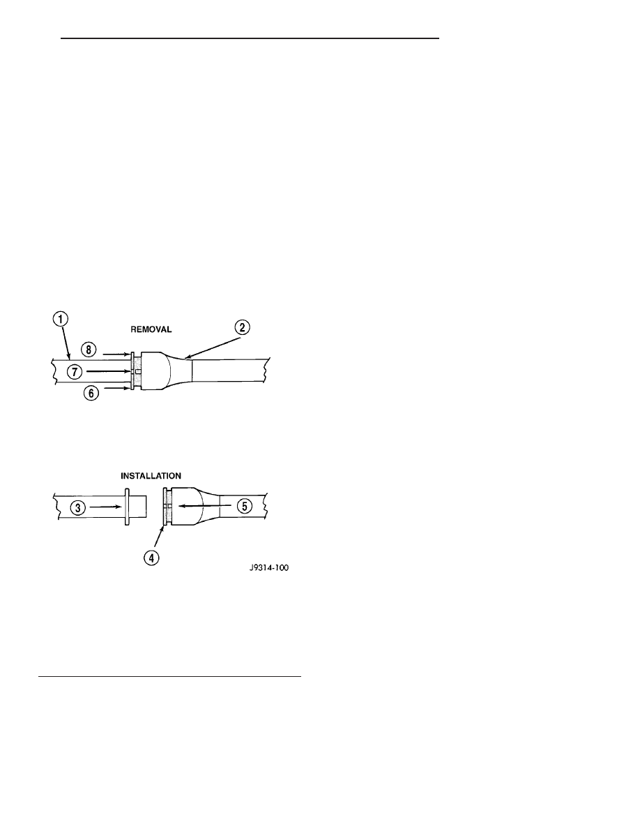
(4) To release fuel system component from quick-

connect fitting, firmly push fitting towards compo-
nent being serviced while firmly pushing plastic
retainer ring into fitting (Fig. 17). With plastic ring
depressed, pull fitting from component. The plastic
retainer ring must be pressed squarely into fit-
ting body. If this retainer is cocked during
removal, it may be difficult to disconnect fit-
ting. Use an open-end wrench on shoulder of
plastic retainer ring to aid in disconnection.

(5) After disconnection, plastic retainer ring will

remain with quick-connect fitting connector body.

(6) Inspect fitting connector body, plastic retainer

ring and fuel system component for damage. Replace
as necessary.

(7) Prior to connecting quick-connect fitting to

component being serviced, check condition of fitting
and component. Clean parts with a lint-free cloth.
Lubricate with clean engine oil.

(8) Insert quick-connect fitting into component

being serviced until a click is felt.

(9) Verify a locked condition by firmly push-pull-

ing-push on fuel tube and fitting (15-30 lbs.).

(10) Connect negative battery cable to battery or

auxiliary jumper terminal.

(11) Use the DRB III

t scan tool ASD Fuel System

Test to pressurize the fuel system. Check for leaks.

Fig. 17 Plastic Retainer Ring Type Fitting

1 - FUEL TUBE
2 - QUICK CONNECT FITTING
3 - PUSH
4 - PLASTIC RETAINER
5 - PUSH
6 - PUSH
7 - PUSH
8 - PUSH

JR

FUEL DELIVERY

14 - 13

QUICK CONNECT FITTING (Continued)

FUEL INJECTION

TABLE OF CONTENTS

page

page

FUEL INJECTION

OPERATION

OPERATION - INJECTION SYSTEM

. . . . . . . 15

OPERATION - MODES OF OPERATION

. . . . 15

FUEL CORRECTION or ADAPTIVE

MEMORIES . . . . . . . . . . . . . . . . . . . . . . . . . . 17

PROGRAMMABLE COMMUNICATIONS

INTERFACE (PCI) BUS . . . . . . . . . . . . . . . . . 18

SYSTEM DIAGNOSIS

. . . . . . . . . . . . . . . . . . 19

SPECIFICATIONS

TORQUE

. . . . . . . . . . . . . . . . . . . . . . . . . . . . 19

SPECIAL TOOLS

FUEL

. . . . . . . . . . . . . . . . . . . . . . . . . . . . . . . 20

ACCELERATOR PEDAL

REMOVAL

. . . . . . . . . . . . . . . . . . . . . . . . . . . . . 20

INSTALLATION

. . . . . . . . . . . . . . . . . . . . . . . . . 21

CRANKSHAFT POSITION SENSOR

DESCRIPTION

. . . . . . . . . . . . . . . . . . . . . . . . . 21

OPERATION

. . . . . . . . . . . . . . . . . . . . . . . . . . . 22

REMOVAL

REMOVAL - 4 CYLINDER

. . . . . . . . . . . . . . . 23

REMOVAL - 2.7L

. . . . . . . . . . . . . . . . . . . . . . 23

INSTALLATION

INSTALLATION - 4 CYLINDER

. . . . . . . . . . . . 23

INSTALLATION - 2.7L

. . . . . . . . . . . . . . . . . . 23

ENGINE SPEED SENSOR

DESCRIPTION

. . . . . . . . . . . . . . . . . . . . . . . . . 24

OPERATION

. . . . . . . . . . . . . . . . . . . . . . . . . . . 24

FUEL INJECTOR

DESCRIPTION

. . . . . . . . . . . . . . . . . . . . . . . . . 24

OPERATION

. . . . . . . . . . . . . . . . . . . . . . . . . . . 24

REMOVAL

REMOVAL - 4 CYLINDER

. . . . . . . . . . . . . . . 24

REMOVAL - 2.7L

. . . . . . . . . . . . . . . . . . . . . . 25

INSTALLATION

INSTALLATION - 4 CYLINDER

. . . . . . . . . . . . 25

INSTALLATION - 2.7L

. . . . . . . . . . . . . . . . . . 25

FUEL PUMP RELAY

DESCRIPTION

. . . . . . . . . . . . . . . . . . . . . . . . . 26

OPERATION

. . . . . . . . . . . . . . . . . . . . . . . . . . . 26

IDLE AIR CONTROL MOTOR

DESCRIPTION

. . . . . . . . . . . . . . . . . . . . . . . . . 26

OPERATION

. . . . . . . . . . . . . . . . . . . . . . . . . . . 26

REMOVAL

REMOVAL - 4 CYLINDER

. . . . . . . . . . . . . . . 27

REMOVAL - 2.7L

. . . . . . . . . . . . . . . . . . . . . . 27

INSTALLATION

INSTALLATION - 4 CYLINDER

. . . . . . . . . . . . 27

INSTALLATION - 2.7L

. . . . . . . . . . . . . . . . . . 27

INLET AIR TEMPERATURE SENSOR

DESCRIPTION

. . . . . . . . . . . . . . . . . . . . . . . . . 28

MAP SENSOR

DESCRIPTION

. . . . . . . . . . . . . . . . . . . . . . . . . 28

OPERATION

. . . . . . . . . . . . . . . . . . . . . . . . . . . 28

REMOVAL

REMOVAL - 4 CYLINDER

. . . . . . . . . . . . . . . 29

REMOVAL - 2.7L

. . . . . . . . . . . . . . . . . . . . . . 29

INSTALLATION

INSTALLATION - 4 CYLINDER

. . . . . . . . . . . . 29

INSTALLATION - 2.7L

. . . . . . . . . . . . . . . . . . 30

O2 SENSOR

DESCRIPTION

. . . . . . . . . . . . . . . . . . . . . . . . . 30

OPERATION

. . . . . . . . . . . . . . . . . . . . . . . . . . . 30

REMOVAL

REMOVAL - DOWNSTREAM 1/2 4

CYLINDER . . . . . . . . . . . . . . . . . . . . . . . . . . . 31

REMOVAL - Downstream 1/2, 2/2 2.7L

. . . . . . 32

REMOVAL - Upstream 1/1, 2/1 2.7L

. . . . . . . . 32

REMOVAL - UPSTREAM 1/1 4 CYLINDER

. . . 32

INSTALLATION

INSTALLATION - DOWNSTREAM 1/2 4

CYLINDER . . . . . . . . . . . . . . . . . . . . . . . . . . . 32

INSTALLATION - Downstream 1/2, 2/2 2.7L

. . 32

INSTALLATION - Upstream 1/1, 2/1 2.7L

. . . . 32

INSTALLATION - UPSTREAM 1/1 4

CYLINDER . . . . . . . . . . . . . . . . . . . . . . . . . . . 33

THROTTLE BODY

DESCRIPTION

. . . . . . . . . . . . . . . . . . . . . . . . . 33

OPERATION

. . . . . . . . . . . . . . . . . . . . . . . . . . . 33

REMOVAL

REMOVAL - 4 CYLINDER

. . . . . . . . . . . . . . . 33

REMOVAL - 2.7L

. . . . . . . . . . . . . . . . . . . . . . 34

INSTALLATION

INSTALLATION - 4 CYLINDER

. . . . . . . . . . . . 35

INSTALLATION - 2.7L

. . . . . . . . . . . . . . . . . . 35

THROTTLE CONTROL CABLE

REMOVAL

. . . . . . . . . . . . . . . . . . . . . . . . . . . . . 35

INSTALLATION

. . . . . . . . . . . . . . . . . . . . . . . . . 36

THROTTLE POSITION SENSOR

DESCRIPTION

. . . . . . . . . . . . . . . . . . . . . . . . . 37

OPERATION

. . . . . . . . . . . . . . . . . . . . . . . . . . . 37

REMOVAL

REMOVAL - 4 CYLINDER

. . . . . . . . . . . . . . . 37

REMOVAL - 2.7L

. . . . . . . . . . . . . . . . . . . . . . 37

INSTALLATION

INSTALLATION - 4 CYLINDER

. . . . . . . . . . . . 37

INSTALLATION - 2.7L

. . . . . . . . . . . . . . . . . . 37

14 - 14

FUEL INJECTION

JR

FUEL INJECTION

OPERATION

OPERATION - INJECTION SYSTEM

All engines used in this section have a sequential

Multi-Port Electronic Fuel Injection system. The MPI
system is computer regulated and provides precise
air/fuel ratios for all driving conditions. The Power-
train Control Module (PCM) operates the fuel injec-
tion system.

The PCM regulates:
• Ignition timing

• Air/fuel ratio

• Emission control devices

• Cooling fan

• Charging system

• Idle speed

• Vehicle speed control
Various sensors provide the inputs necessary for

the PCM to correctly operate these systems. In addi-
tion to the sensors, various switches also provide
inputs to the PCM.

The PCM can adapt its programming to meet

changing operating conditions.

Fuel is injected into the intake port above the

intake valve in precise metered amounts through
electrically operated injectors. The PCM fires the
injectors in a specific sequence. Under most operat-
ing conditions, the PCM maintains an air fuel ratio
of 14.7 parts air to 1 part fuel by constantly adjust-
ing injector pulse width. Injector pulse width is the
length of time the injector is open.

The PCM adjusts injector pulse width by opening

and closing the ground path to the injector. Engine
RPM (speed) and manifold absolute pressure (air
density) are the primary inputs that determine
injector pulse width.

OPERATION - MODES OF OPERATION

As input signals to the PCM change, the PCM

adjusts its response to output devices. For example,
the PCM must calculate a different injector pulse
width and ignition timing for idle than it does for
Wide Open Throttle (WOT). There are several differ-
ent modes of operation that determine how the PCM
responds to the various input signals.

There are two different areas of operation, OPEN

LOOP and CLOSED LOOP.

During OPEN LOOP modes the PCM receives

input signals and responds according to preset PCM
programming. Inputs from the upstream and down-
stream heated oxygen sensors are not monitored dur-
ing OPEN LOOP modes, except for heated oxygen

sensor diagnostics (they are checked for shorted con-
ditions at all times).

During CLOSED LOOP modes the PCM monitors

the inputs from the upstream and downstream
heated oxygen sensors. The upstream heated oxygen
sensor input tells the PCM if the calculated injector
pulse width resulted in the ideal air-fuel ratio of 14.7
to one. By monitoring the exhaust oxygen content
through the upstream heated oxygen sensor, the
PCM can fine tune injector pulse width. Fine tuning
injector pulse width allows the PCM to achieve opti-
mum fuel economy combined with low emissions.

For the PCM to enter CLOSED LOOP operation,

the following must occur:

(1) Engine coolant temperature must be over 35°F.
• If the coolant is over 35°F the PCM will wait 38

seconds.

• If the coolant is over 50°F the PCM will wait 15

seconds.

• If the coolant is over 167°F the PCM will wait 3

seconds.

(2) For other temperatures the PCM will interpo-

late the correct waiting time.

(3) O2 sensor must read either greater than 0.745

volts or less than 0.29 volt.

(4) The multi-port fuel injection systems has the

following modes of operation:

• Ignition switch ON (Zero RPM)

• Engine start-up

• Engine warm-up

• Cruise

• Idle

• Acceleration

• Deceleration

• Wide Open Throttle

• Ignition switch OFF
(5) The engine start-up (crank), engine warm-up,

deceleration with fuel shutoff and wide open throttle
modes are OPEN LOOP modes. Under most operat-
ing conditions, the acceleration, deceleration (with
A/C on), idle and cruise modes, with the engine at
operating temperature 
are CLOSED LOOP modes.

IGNITION SWITCH ON (ZERO RPM) MODE

When the ignition switch activates the fuel injec-

tion system, the following actions occur:

• The PCM monitors the engine coolant tempera-

ture sensor and throttle position sensor input. The
PCM determines basic fuel injector pulse width from
this input.

• The PCM determines atmospheric air pressure

from the MAP sensor input to modify injector pulse
width.

JR

FUEL INJECTION

14 - 15

When the key is in the ON position and the engine

is not running (zero rpm), the Auto Shutdown (ASD)
and fuel pump relays de-energize after approximately
1 second. Therefore, battery voltage is not supplied to
the fuel pump, ignition coil, fuel injectors and heated
oxygen sensors.

ENGINE START-UP MODE

This is an OPEN LOOP mode. If the vehicle is in

park or neutral (automatic transaxles) or the clutch
pedal is depressed (manual transaxles) the ignition
switch energizes the starter relay when the engine is
not running. The following actions occur when the
starter motor is engaged.

• If the PCM receives the camshaft position sensor

and crankshaft position sensor signals, it energizes
the Auto Shutdown (ASD) relay and fuel pump relay.
If the PCM does not receive both signals within
approximately one second, it will not energize the
ASD relay and fuel pump relay. The ASD and fuel
pump relays supply battery voltage to the fuel pump,
fuel injectors, ignition coil, (EGR solenoid and PCV
heater if equipped) and heated oxygen sensors.

• The PCM energizes the injectors (on the 69°

degree falling edge) for a calculated pulse width until
it determines crankshaft position from the camshaft
position sensor and crankshaft position sensor sig-
nals. The PCM determines crankshaft position within
1 engine revolution.

• After determining crankshaft position, the PCM

begins energizing the injectors in sequence. It adjusts
injector pulse width and controls injector synchroni-
zation by turning the individual ground paths to the
injectors On and Off.

• When the engine idles within ±64 RPM of its

target RPM, the PCM compares current MAP sensor
value with the atmospheric pressure value received
during the Ignition Switch On (zero RPM) mode.

Once the ASD and fuel pump relays have been

energized, the PCM determines injector pulse width
based on the following:

• MAP

• Engine RPM

• Battery voltage

• Engine coolant temperature

• Inlet/Intake air temperature (IAT)

• Throttle position

• The number of engine revolutions since cranking

was initiated

During Start-up the PCM maintains ignition tim-

ing at 9° BTDC.

ENGINE WARM-UP MODE

This is an OPEN LOOP mode. The following inputs

are received by the PCM:

• Manifold Absolute Pressure (MAP)

• Crankshaft position (engine speed)

• Engine coolant temperature

• Inlet/Intake air temperature (IAT)

• Camshaft position

• Knock sensor

• Throttle position

• A/C switch status

• Battery voltage

• Vehicle speed

• Speed control

• O2 sensors
The PCM adjusts injector pulse width and controls

injector synchronization by turning the individual
ground paths to the injectors On and Off.

The PCM adjusts ignition timing and engine idle

speed. Engine idle speed is adjusted through the idle
air control motor.

CRUISE OR IDLE MODE

When the engine is at operating temperature this

is a CLOSED LOOP mode. During cruising or idle
the following inputs are received by the PCM:

• Manifold absolute pressure

• Crankshaft position (engine speed)

• Inlet/Intake air temperature

• Engine coolant temperature

• Camshaft position

• Knock sensor

• Throttle position

• Exhaust gas oxygen content (O2 sensors)

• A/C switch status

• Battery voltage

• Vehicle speed
The PCM adjusts injector pulse width and controls

injector synchronization by turning the individual
ground paths to the injectors On and Off.

The PCM adjusts engine idle speed and ignition

timing. The PCM adjusts the air/fuel ratio according
to the oxygen content in the exhaust gas (measured
by the upstream and downstream heated oxygen sen-
sor).

The PCM monitors for engine misfire. During

active misfire and depending on the severity, the
PCM either continuously illuminates or flashes the
malfunction indicator lamp (Check Engine light on
instrument panel). Also, the PCM stores an engine
misfire DTC in memory, if 2nd trip with fault.

The PCM performs several diagnostic routines.

They include:

• Oxygen sensor monitor

• Downstream heated oxygen sensor diagnostics

during open loop operation (except for shorted)

• Fuel system monitor

• EGR monitor (if equipped)

• Purge system monitor

• Catalyst efficiency monitor

14 - 16

FUEL INJECTION

JR

FUEL INJECTION (Continued)


Content   ..  542  543  544  545   ..