Chrysler Sebring, Stratus sedan, Sebring Convertible. Manual - part 543


  Index      Chrysler     Chrysler Sebring, Stratus sedan, Sebring Convertible - service repair manual 2001-2007 year


Search            


Content   ..  541  542  543  544   ..


Chrysler Sebring, Stratus sedan, Sebring Convertible. Manual - part 543


(7) Install fuel rail support bracket and loosely

install all bolts (Fig. 10).

(8) Tighten three fasteners to intake manifold to

28.3 N·m (250 in. lbs.) torque.

(9) Tighten two bolts to fuel rail to 8.5 N·m (75 in.

lbs.) torque.

(10) Install wiring harness to brackets (Fig. 11).
(11) Connect the throttle and speed control cables

to fuel rail bracket (Fig. 12).

(12) Connect negative battery cable.
(13) Use the DRBIII

t scan tool to pressurize the

fuel system. Check for leaks.

INSTALLATION - 2.7L

(1) Lightly lubricate the fuel injector O-rings with

a couple drops of clean engine oil.

(2) Install retaining clips on fuel injectors.
(3) Push injectors into fuel injector rail until clips

are in the correct position.

(4) Position fuel rail over cylinder heads, and push

rail into place. Tighten fuel rail mounting bolts to
11.9 N·m (105 in. lbs.) torque.

(5) Connect the fuel supply tube quick connect fit-

ting to the fuel rail. Refer to Quick Connect Fittings
in the Fuel Delivery Section.

(6) Connect the electrical connectors to the fuel

injectors.

(7) Install intake manifold plenum. Refer to the

Engine section for information.

(8) Connect negative cable to battery.
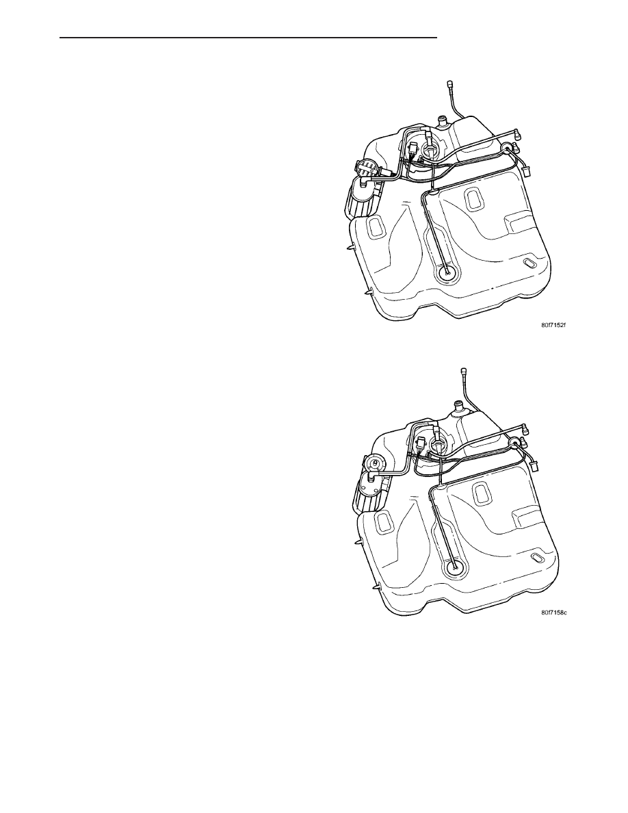
FUEL TANK

DESCRIPTION

The fuel tank is constructed of a plastic material.

Its main functions are for fuel storage and for place-
ment of the fuel pump module. The tank is made
from High density Polyethylene (HDPE) material. If
equipped with ORVR (Onboard Refueling Vapor
Recovery) it has been added to the fuel tank to con-
trol refueling vapor emissions.

The PZEV (Partial Zero Emission Vehicle) fuel

tank is a steel tank with the check valves, and hoses
inside of the tank. This system uses the NVLD (Nat-
ural Vacuum Leak Detection) system for leak detec-
tion for both plastic and steel tanks.

OPERATION

All models pass a full 360 degree rollover test

without fuel leakage. To accomplish this, fuel and
vapor flow controls are required for all fuel tank con-
nections.

All models are equipped with either one or two

check valves mounted into the top of the fuel tank (or
pump module). On the PZEV system the check valves
are inside of the fuel tank. The valves are non-ser-
viceable parts.

NVLD FUEL TANK

NON US FUEL TANK

JR

FUEL DELIVERY

14 - 9

FUEL RAIL (Continued)

An evaporation control system is connected to the

check valve(s)/control valve(Refer to 25 - EMIS-
SIONS

CONTROL/EVAPORATIVE

EMISSIONS/

ORVR - OPERATION) to reduce emissions of fuel
vapors into the atmosphere, when the tank is vented
due to vapor expansion in the tank. When fuel evap-
orates from the fuel tank, vapors pass through vent
hoses or tubes to a charcoal canister where they are
temporarily held. When the engine is running, the
vapors are drawn into the intake manifold. In addi-
tion, fuel vapors produced during vehicle refueling
are allowed to pass through the vent hoses/tubes to
the charcoal canister(s) for temporary storage (prior
to being drawn into the intake manifold). All models
are equipped with a self-diagnosing system using a
Leak Detection Pump (LDP) or Natural Vacuum
Leak Detection (NVLD). Refer to the Emission Con-
trol System for additional information.

INLET CHECK VALVE

All vehicles have an inlet check valve on the inside

of the fuel tank at the filler inlet

The valve prevents fuel from splashing back on

customer during vehicle refueling. The valve is a
non-serviceable item.

REMOVAL

(1) Remove fuel filler cap and perform Fuel Sys-

tem Pressure Release procedure.

(2) Disconnect negative cable from battery.
(3) Drain fuel tank dry into holding tank or a

properly labeled GASOLINE safety container.

(4) Raise vehicle on hoist and support.
(5) Use a transmission jack to support fuel tank.

Remove bolts from fuel tank straps.

(6) Lower tank slightly.
(7) Disconnect the fuel filler vent tube.
(8) Disconnect fuel line and vapor line.
(9) Disconnect the vacuum line from the LDP.
(10) Disconnect fuel filler tube by loosing the

clamp and removing hose.

(11) Slide fuel pump module electrical connector

lock to unlock. The fuel pump module electrical
connector has a retainer that locks it in place
.

(12) Push down on connector retainer and pull

connector off module.

(13) Lower tank from vehicle.

INSTALLATION

(1) Position fuel tank on transmission jack.
(2) Raise tank into position and carefully work

filler tube onto the fuel tank. A light coating of clean
engine oil on the tube end may be used to aid assem-
bly. Connect fuel filler tube hose and tighten clamp.

(3) Connect fuel pump/module electrical connector.

Place retainer in locked position.

(4) Connect the EVAP, vapor, and vacuum lines.
(5) Lubricate the fuel supply line with clean 30

weight engine oil, install the quick connect fuel fit-
ting. Refer to Tube/Fitting Assembly in the Fuel
Delivery section of this section.

(6) Attach filler vent line to filler tube. Pull on

connector to make sure of connection.

(7) Place NVLD air filter under right rear tank

strap before tightening.

(8) Tighten strap bolts to 54 N·m (40 ft. lbs.)

torque. Remove transmission jack.

(9) Tighten filler hose clamp to 3.6 N·m (31.8 in.

lbs.).

CAUTION: Ensure straps are not twisted or bent
before or after tightening strap nuts.

(10) Fill fuel tank, replace cap, and connect bat-

tery negative cable.

(11) Use the DRBIII

t scan tool to pressurize the

fuel system. Check for leaks.

PZEV FUEL TANK

14 - 10

FUEL DELIVERY

JR

FUEL TANK (Continued)

FUEL TANK FILLER TUBE

REMOVAL

(1) Disconnect negative cable from battery.
(2) Drain fuel tank.
(3) Remove 3 screws from filler neck to quarter

panel (Fig. 14).

(4) Raise and support vehicle on host.
(5) Remove the ground strap.
(6) Loosen clamps at filler neck.
(7) Remove filler neck from the fuel tank.
(8) Use transmission jack to support the fuel tank.
(9) Remove the rear bolts for fuel tank straps.
(10) Lower the fuel tank enough to reach the filler

tube vent line connection.

(11) Disconnect the filler tube vent line.
(12) Remove the fuel filler tube.

INSTALLATION

(1) Install filler neck to filler hose.
(2) Connect the fuel filler vent tube.
(3) Raise fuel tank into position.
(4) Install fuel tank straps and tighten bolts to 54

N·m (39.8 ft. lbs).

(5) Remove the transmission jack.
(6) Tighten clamps 3.6 N·m (31.8 in. lbs.).
(7) Install ground strap 8.4 N·m (75 in. lbs.).
(8) Lower vehicle.
(9) Install 3 screws to filler neck and quarter panel

(Fig. 14) 2.3 N·m (21 in. lbs.).

(10) Fill tank and check for leaks.
(11) Connect negative cable from battery.

FUEL TANK VENT TUBE

REMOVAL

(1) Perform fuel system pressure release.
(2) Disconnect negative cable from battery.
(3) Drain fuel tank.
(4) Raise and support vehicle on host.
(5) Lower fuel tank, refer to Fuel Tank Removal/

Installation in this section.

(6) Remove vent hose from top of tank.
(7) Remove vent hose from fuel filler neck.

INSTALLATION

(1) Install vent hose and tighten clamp.
(2) Install fuel tank, refer to Fuel Tank Removal/

Installation in this section.

(3) Install vent hose to fuel filler neck and tighten

clamp.

(4) Lower vehicle.
(5) Fill fuel tank and check for leaks.
(6) Connect negative cable to battery.

QUICK CONNECT FITTING

STANDARD PROCEDURE - QUICK-CONNECT
FITTINGS

REMOVAL

When disconnecting a quick-connect fitting, the

retainer will remain on the fuel tube nipple.

WARNING: RELEASE FUEL SYSTEM PRESSURE
BEFORE DISCONNECTING A QUICK-CONNECT FIT-
TINGS. REFER TO THE FUEL PRESSURE RELEASE
PROCEDURE. THIS MAY RESULT IN PERSONAL
INJURY OR DEATH.

(1) Perform

Fuel

Pressure

Release

Procedure.

Refer to the Fuel Pressure Release Procedure in this
section.

(2) Disconnect negative cable from battery or aux-

iliary jumper terminal.

(3) Squeeze retainer tabs together and pull fuel

tube/quick-connect fitting assembly off of fuel tube
nipple. The retainer will remain on fuel tube.

INSTALLATION

CAUTION: Make sure that the o-ring in installed in
fitting. Never install a quick-connect fitting without
the retainer being either on the fuel tube or already
in the quick-connect fitting. In either case, ensure
the retainer locks securely into the quick-connect
fitting by firmly push-pulling-push on fuel tube and
fitting to ensure it is secured.

Fig. 14 FILLER DOOR

JR

FUEL DELIVERY

14 - 11

(1) Using a clean lint free cloth, clean the fuel tube

nipple and retainer.

(2) Prior to connecting the fitting to the fuel tube,

coat the fuel tube nipple with clean engine oil.

(3) Push the quick-connect fitting over the fuel

tube until the retainer seats and a click is heard.

(4) The plastic quick-connect fitting has windows

in the sides of the casing. When the fitting com-
pletely attaches to the fuel tube, the retainer locking
ears and the fuel tube shoulder are visible in the
windows. If they are not visible, the retainer was not
properly installed (Fig. 15). Do not rely upon the
audible click to confirm a secure connection.

(5) Connect negative cable to battery or auxiliary

jumper terminal.

CAUTION: When using the ASD Fuel System Test,
the Auto Shutdown (ASD) Relay remains energized
for several minutes, until the test is stopped, or
until the ignition switch is turned to the Off posi-
tion.

(6) Use the DRB III

t scan tool ASD Fuel System

Test to pressurize the fuel system. Check for leaks.

TWO-TAB TYPE FITTING

This type of fitting is equipped with tabs located on

both sides of the fitting (Fig. 16). These tabs are sup-
plied for disconnecting the quick-connect fitting from
component being serviced.

CAUTION: The interior components (O-rings, spac-
ers) of this type of quick-connect fitting are not ser-
viced separately, but new plastic retainers are
available. Do not attempt to repair damaged fittings
or fuel lines/tubes. If repair is necessary, replace
the complete fuel tube assembly.

WARNING: THE FUEL SYSTEM IS UNDER A CON-
STANT PRESSURE (EVEN WITH THE ENGINE OFF).
BEFORE SERVICING ANY FUEL SYSTEM HOSES,
FITTINGS OR LINES, THE FUEL SYSTEM PRES-
SURE MUST BE RELEASED. REFER TO THE FUEL
PRESSURE

RELEASE

PROCEDURE

IN

THIS

GROUP. THIS MAY RESULT IN PERSONAL INJURY
OR DEATH.

DISCONNECTION/CONNECTION

(1) Perform fuel pressure release procedure. Refer

to Fuel Pressure Release Procedure in this group.

(2) Disconnect negative battery cable from battery

or auxiliary jumper terminal.

(3) Clean fitting of any foreign material before dis-

assembly.

(4) To disconnect quick-connect fitting, squeeze

plastic retainer tabs (Fig. 16) against sides of quick-
connect fitting with your fingers. Tool use is not
required

for

removal

and

may

damage

plastic

retainer. Pull fitting from fuel system component
being serviced. The plastic retainer will remain on
component being serviced after fitting is discon-
nected. The O-rings and spacer will remain in quick-
connect fitting connector body.

(5) Inspect quick-connect fitting body and compo-

nent for damage. Replace as necessary.

CAUTION: When the quick-connect fitting was dis-
connected, the plastic retainer will remain on the
component being serviced. If this retainer must be
removed, very carefully release the retainer from
the component with two small screwdrivers. After
removal, inspect the retainer for cracks or any dam-
age.

Fig. 15 Plastic Quick-Connect Fitting/Fuel Tube

Connection

1 - WINDOW
2 - TAB (2)
3 - EAR
4 - SHOULDER (ON TUBE)

Fig. 16 Typical Two-Tab Type Quick-Connect Fitting

1 - TAB(S)
2 - QUICK-CONNECT FITTING

14 - 12

FUEL DELIVERY

JR

QUICK CONNECT FITTING (Continued)


Content   ..  541  542  543  544   ..