Chrysler Sebring, Stratus sedan, Sebring Convertible. Manual - part 535
INSPECTION
Inspect the exhaust pipes, catalytic converters,
muffler, and resonators for cracked joints, broken
welds and corrosion damage that would result in a
leaking exhaust system. Inspect the clamps, support
brackets, and insulators for cracks and corrosion
damage.
NOTE: Slip joint band clamps are spot welded to
exhaust system. If a band clamp must be replaced,
the spot weld must be ground off.
INSTALLATION - EXHAUST SYSTEM
NOTE: Always work from the front to rear of
exhaust
system
when
aligning
and
tightening
exhaust system components.
(1) Loosely install fasteners that attach exhaust
system to exhaust manifold (2.0L/2.4L)/cross-under
pipe (2.7L).
(2) Install support isolators to muffler supports.
(3) Align exhaust system to maintain position and
proper clearance with underbody parts. All support
isolators should have equal load on them. Tighten
fasteners that attach exhaust system to exhaust
manifold (2.0L/2.4L)/cross-under pipe (2.7L) to 28
N·m (250 in. lbs.).
(4) Vehicles
equipped
with
2.0L/2.4L
engines,
reconnect the downstream oxygen sensor connector.
(5) Connect ground strap to muffler.
(6) Lower vehicle.
(7) Start the engine and inspect for exhaust leaks.
Repair exhaust leaks as necessary.
(8) Check the exhaust system for contact with the
body panels. Make the necessary ajustments, if
needed.
ADJUSTMENTS
A misaligned exhaust system is usually indicated
by a vibration, rattling noise, or binding of exhaust
system components. These noises are sometimes hard
to distinguish from other chassis noises. Inspect
exhaust system for broken or loose clamps, heat
shields, isolators, and brackets. Replace or tighten as
necessary. It is important that exhaust system clear-
ances and alignment be maintained.
Perform the following procedures to align the
exhaust system:
(1) Loosen clamps and support brackets.
(2) Align the exhaust system starting at the front,
working rearward.
(3) Tighten all clamps and brackets once align-
ment and clearances are achieved.
SPECIFICATIONS
TORQUE
DESCRIPTION
N·m
Ft.
Lbs.
In.
Lbs.
Band Clamps—Fastener
54
40
—
Body Heat Shield—Fasteners
5
—
40
Catalytic Converter to Exhaust
Manifold Flange—Fasteners
28
—
250
Cross-Under Pipe —Fasteners (2.7L)
28
—
250
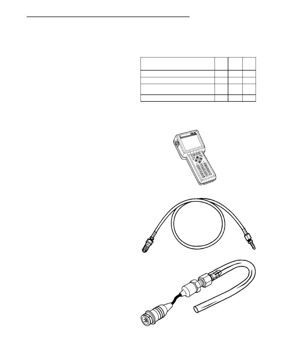
SPECIAL TOOLS
EXHAUST SYSTEM
DRB III & PEP Module - OT-CH6010A
Back Pressure Test Adapter - CH8519
Pressure Transducer CH7063
JR
EXHAUST SYSTEM
11 - 5
EXHAUST SYSTEM (Continued)