Chrysler Sebring, Stratus sedan, Sebring Convertible. Manual - part 509


  Index      Chrysler     Chrysler Sebring, Stratus sedan, Sebring Convertible - service repair manual 2001-2007 year


Search            


Content   ..  507  508  509  510   ..


Chrysler Sebring, Stratus sedan, Sebring Convertible. Manual - part 509


(2) Remove Timing Belt (Refer to 9 - ENGINE/

VALVE TIMING/TIMING BELT AND SPROCKETS -
REMOVAL).

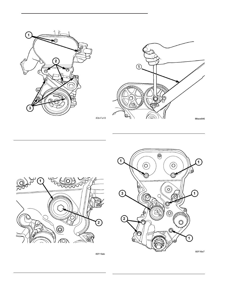
(3) Remove timing belt idler pulley (Fig. 111).

(4) Remove both camshaft sprockets. Hold cam-

shaft sprockets with Special Tool 6847 while remov-
ing center bolts (Fig. 112).

(5) Remove rear timing belt cover fasteners and

remove cover from engine (Fig. 113).

Fig. 110 Front Timing Belt Covers

1 - UPPER TIMING BELT COVER FASTENERS
2 - ENGINE SUPPORT BRACKET FASTENERS
3 - LOWER TIMING BELT COVER FASTENERS

Fig. 111 Timing Belt Idler Pulley

1 - IDLER PULLEY
2 - BOLT

Fig. 112 Camshaft Sprocket - Removal/Installation

1 - SPECIAL TOOL 6847

Fig. 113 Rear Timing Belt Cover Fasteners

1 - M6 BOLTS - 12 N·m (105 in. lbs.)
2 - M8 BOLTS - 28 N·m (250 in. lbs.)
3 - TIMING BELT TENSIONER

JR

ENGINE 2.4L DOHC

9 - 139

TIMING BELT COVER(S) (Continued)

INSTALLATION

FRONT COVER - UPPER

(1) Install timing belt cover. Torque fasteners to 6

N·m (50 in. lbs.) (Fig. 110).

FRONT COVER - LOWER

(1) Install lower timing belt cover and torque fas-

teners to 6 N·m (50 in. lbs.) (Fig. 110).

(2) Lower vehicle.
(3) Install generator and bracket.
(4)

Connect generator connectors.

(5) Raise vehicle.
(6) Install AC/Generator belt tensioner.
(7) Install

crankshaft

damper

(Refer

to

9

-

ENGINE/ENGINE BLOCK/VIBRATION DAMPER -
INSTALLATION).

(8) Install accessory drive belts (Refer to 7 -

COOLING/ACCESSORY

DRIVE/DRIVE

BELTS

-

INSTALLATION).

(9) Install belt splash shield and right front wheel.
(10) Lower vehicle.
(11) Connect negative battery cable.

REAR COVER

(1) Install rear timing belt cover and fasteners.

Torque fasteners to specified values (Fig. 113).

(2) Install

camshaft

sprockets.

Hold

camshaft

sprockets with Special Tool 6847 while tightening
center bolts to 115 N·m (85 ft. lbs) (Fig. 112).

(3) Install timing belt idler pulley (Fig. 111).
(4) Install timing belt (Refer to 9 - ENGINE/

VALVE TIMING/TIMING BELT AND SPROCKETS -
INSTALLATION).

(5) Install upper and lower front timing belt cov-

ers.

TIMING BELT AND
SPROCKET(S)

REMOVAL

REMOVAL - TIMING BELT

(1) Disconnect negative battery cable.
(2) Raise vehicle on hoist. Remove right front

wheel.

(3) Remove belt splash shield.
(4) Remove accessory drive belts (Refer to 7 -

COOLING/ACCESSORY

DRIVE/DRIVE

BELTS

-

REMOVAL).

(5) Remove crankshaft damper (Refer to 9 -

ENGINE/ENGINE BLOCK/VIBRATION DAMPER -
REMOVAL).

(6) Remove AC/Generator belt tensioner.

(7) Disconnect generator connections. Remove gen-

erator and bracket.

(8) Remove upper and lower timing belt covers

(Refer to 9 - ENGINE/VALVE TIMING/TIMING
BELT COVER(S) - REMOVAL) (Fig. 110).

(9) Remove coolant recovery container (Refer to 7 -

COOLING/ENGINE/COOLANT RECOVERY CON-
TAINER - REMOVAL).

(10)

Remove right engine mount (Refer to 9 -

ENGINE/ENGINE MOUNTING/RIGHT MOUNT -
REMOVAL).

(11) Remove engine support bracket (Fig. 110).

CAUTION: When aligning crankshaft and camshaft
timing marks always rotate engine from crankshaft.
Camshaft should not be rotated after timing belt is
removed. Damage to valve components may occur.
Always align timing marks before removing timing
belt.

(12) Before the removal of the timing belt, rotate

crankshaft until the TDC mark on oil pump housing
aligns with the TDC mark on crankshaft sprocket
(trailing edge of sprocket tooth) (Fig. 114).

NOTE:

The

crankshaft

sprocket

TDC

mark

is

located on the trailing edge of the sprocket tooth.
Failure to align trailing edge of sprocket tooth to
TDC mark on oil pump housing will cause the cam-
shaft timing marks to be misaligned.

(13) Loosen timing belt tensioner lock bolt (Fig.

115).

(14) Insert a 6 mm Allen wrench into the hexagon

opening located on the top plate of the belt tensioner
pulley (Fig. 115). Rotate the top plate CLOCKWISE
until there is enough slack in timing belt to allow for
removal.

(15) Remove timing belt.

CAUTION: If timing belt was damaged due to incor-
rect tracking (alignment), the belt tensioner pulley
and bracket must be replaced as an assembly
(Refer to 9 - ENGINE/VALVE TIMING/TIMING BELT
TENSIONER & PULLEY - REMOVAL).

REMOVAL - CAMSHAFT SPROCKETS

(1) Disconnect negative battery cable.
(2) Remove timing belt (Refer to 9 - ENGINE/

VALVE TIMING/TIMING BELT AND SPROCKETS -
REMOVAL).

(3) Hold camshaft sprockets with Special Tool 6847

while removing center bolts (Fig. 116).

REMOVAL - CRANKSHAFT SPROCKET

(1) Disconnect negative battery cable.

9 - 140

ENGINE 2.4L DOHC

JR

TIMING BELT COVER(S) (Continued)

(2) Remove timing belt (Refer to 9 - ENGINE/

VALVE TIMING/TIMING BELT AND SPROCKETS -
REMOVAL).

(3) Remove

crankshaft

sprocket

using

Special

Tools 6793 and insert C-4685-C2 (Fig. 117).

CLEANING

Do Not attempt to clean a timing belt. If contami-

nation from oil, grease, or coolants have occurred, the
timing belt should be replaced.

Clean all sprockets using a suitable solvent. Clean

all sprocket grooves of any debris.

Fig. 114 Crankshaft and Camshaft Timing

1 - CAMSHAFT TIMING MARKS
2 - CRANKSHAFT TDC MARKS
3 - TRAILING EDGE OF SPROCKET TOOTH

Fig. 115 Timing Belt Tensioner

1 - LOCK BOLT
2 - TOP PLATE

Fig. 116 Camshaft Sprocket - Removal/Installation

1 - SPECIAL TOOL 6847

Fig. 117 Crankshaft Sprocket - Removal

1 - SPECIAL TOOL 6793
2 - SPECIAL TOOL C-4685–C2
3 - CRANKSHAFT SPROCKET

JR

ENGINE 2.4L DOHC

9 - 141

TIMING BELT AND SPROCKET(S) (Continued)

INSTALLATION

INSTALLATION - CRANKSHAFT SPROCKET

CAUTION: The crankshaft sprocket is set to a pre-
determined depth from the factory for correct tim-
ing belt tracking. If removed, use of Special Tool
6792 is required to set the sprocket to original
installation depth. An incorrectly installed sprocket
will result in timing belt and engine damage.

(1) Install crankshaft sprocket using Special Tool

6792 (Fig. 118).

(2) Install timing belt. (Refer to 9 - ENGINE/

VALVE TIMING/TIMING BELT AND SPROCKETS -
INSTALLATION).

(3) Connect negative battery cable.

INSTALLATION - CAMSHAFT SPROCKETS

(1) Install

camshaft

sprockets.

Hold

camshaft

sprockets with Special Tool 6847 while tightening
center bolts to 115 N·m (85 ft. lbs.) (Fig. 116).

(2) Install timing belt (Refer to 9 - ENGINE/

VALVE TIMING/TIMING BELT AND SPROCKETS -
INSTALLATION).

(3) Connect negative battery cable.

INSTALLATION - TIMING BELT

(1)

Set crankshaft sprocket to TDC by aligning

the sprocket with the arrow on the oil pump housing.

(2)

Set camshafts timing marks so that the

exhaust camshaft sprocket is a 1/2 notch below the
intake camshaft sprocket (Fig. 119).

CAUTION: Ensure that the arrows on both camshaft
sprockets are facing up.

(3) Install timing belt. Starting at the crankshaft,

go around the water pump sprocket, idler pulley,
camshaft sprockets and then around the tensioner
(Fig. 120).

(4)

Move the exhaust camshaft sprocket counter-

clockwise (Fig. 120) to align marks and take up belt
slack.

(5) Insert a 6 mm Allen wrench into the hexagon

opening located on the top plate of the belt tensioner
pulley. Rotate the top plate COUNTERCLOCK-
WISE
. The tensioner pulley will move against the
belt and the tensioner setting notch will eventually
start to move clockwise. Watching the movement of
the setting notch, continue rotating the top plate
counterclockwise until the setting notch is aligned
with the spring tang (Fig. 121). Using the allen
wrench to prevent the top plate from moving, torque
the tensioner lock bolt to 25 N·m (220 in. lbs.). Set-
ting notch and spring tang should remain aligned
after lock nut is torqued.

(6) Remove allen wrench and torque wrench.

NOTE: Repositioning the crankshaft to the TDC
position must be done only during the CLOCKWISE
rotation movement. If TDC is missed, rotate a fur-
ther two revolutions until TDC is achieved. DO NOT
rotate crankshaft counterclockwise as this will
make verification of proper tensioner setting impos-
sible.

(7) Rotate the crankshaft CLOCKWISE two com-

plete revolutions manually for seating of the belt,
until the crankshaft is repositioned at the TDC posi-
tion. Verify that the camshaft and crankshaft timing
marks are in proper position (Fig. 122).

(8) Check if the spring tang is within the tolerance

window (Fig. 123). If the spring tang is within the

Fig. 118 Crankshaft Sprocket—Installation

1 - SPECIAL TOOL 6792
2 - TIGHTEN NUT TO INSTALL

Fig. 119 Camshaft Sprocket Alignment

1 - CAMSHAFT SPROCKET-EXHAUST
2 - CAMSHAFT SPROCKET-INTAKE
3 - 1/2 NOTCH LOCATION

9 - 142

ENGINE 2.4L DOHC

JR

TIMING BELT AND SPROCKET(S) (Continued)


Content   ..  507  508  509  510   ..