Chrysler Sebring, Stratus sedan, Sebring Convertible. Manual - part 482


  Index      Chrysler     Chrysler Sebring, Stratus sedan, Sebring Convertible - service repair manual 2001-2007 year


Search            


Content   ..  480  481  482  483   ..


Chrysler Sebring, Stratus sedan, Sebring Convertible. Manual - part 482


(4) Remove camshaft sprockets and rear timing

belt cover (Refer to 9 - ENGINE/VALVE TIMING/
TIMING BELT / CHAIN COVER(S) - REMOVAL).

(5) Bearing

caps

are

identified

for

location.

Remove the outside bearing caps first (Fig. 21).

(6)

Loosen the camshaft bearing cap attaching

fasteners in sequence shown (Fig. 22) one camshaft
at a time.

CAUTION: Camshafts are not interchangeable. The
intake cam number 6 thrust bearing face spacing is
wider.

(7) Identify the camshafts before removing from

the head. The camshafts are not interchangeable.

(8) Remove camshafts from cylinder head.

NOTE: If removing rocker arms, identify for reinstal-
lation in the original position.

CLEANING

Clean camshaft with a suitable solvent.

INSPECTION

(1) Inspect camshaft bearing journals for damage

and binding (Fig. 23). If journals are binding, check

the cylinder head for damage. Also check cylinder
head oil holes for clogging.

(2) Check the cam lobe and bearing surfaces for

abnormal wear and damage. Replace camshaft if
defective.

NOTE: If camshaft is replaced due to lobe wear or
damage, always replace the rocker arms.

(3) Measure the lobe actual wear (unworn area -

wear zone = actual wear) (Fig. 23) and replace cam-
shaft if out of limit. Standard value is 0.0254 mm
(0.001 in.), wear limit is 0.254 mm (0.010 in.).

INSTALLATION

CAUTION: Ensure that NONE of the pistons are at
top dead center when installing the camshafts.

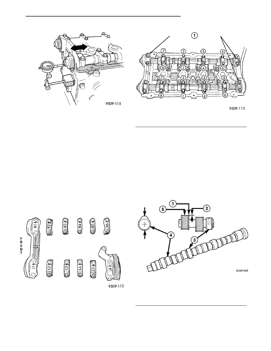
Fig. 20 Camshaft End Play - Typical

Fig. 21 Camshaft Bearing Cap Identification

Fig. 22 Camshaft Bearing Cap - Removal

1 - REMOVE OUTSIDE BEARING CAPS FIRST

Fig. 23 Checking Camshaft(s) for Wear

1 - UNWORN AREA
2 - ACTUAL WEAR
3 - BEARING JOURNAL
4 - LOBE
5 - WEAR ZONE

JR

ENGINE 2.0L DOHC

9 - 31

CAMSHAFT(S) (Continued)

(1) Lubricate all camshaft bearing journals, rocker

arms and camshaft lobes.

(2) Install all rocker arms in original positions, if

reused.

(3) Position camshafts on cylinder head bearing

journals. Install right and left camshaft bearing caps
No. 2 – 5 and right No. 6. Tighten M6 fasteners to 12
N·m (105 in. lbs.) in sequence shown in (Fig. 24).

(4) Apply Mopar

t Gasket Maker to No. 1 and No.

6 bearing caps (Fig. 25). Install bearing caps and
tighten M8 fasteners to 28 N·m (250 in. lbs.).

NOTE: Bearing end caps must be installed before
seals can be installed.

(5) Install

camshaft

oil

seals

(Refer

to

9

-

ENGINE/CYLINDER

HEAD/CAMSHAFT

OIL

SEAL(S) - INSTALLATION).

(6) Install camshaft target magnet and camshaft

position sensor.

(7) Install cylinder head cover (Refer to 9 -

ENGINE/CYLINDER

HEAD/CYLINDER

HEAD

COVER(S) - INSTALLATION).

(8) Install rear timing belt cover and camshaft

sprockets (Refer to 9 - ENGINE/VALVE TIMING/

TIMING BELT / CHAIN COVER(S) - INSTALLA-
TION).

(9) Install timing belt and front timing belt cover

(Refer to 9 - ENGINE/VALVE TIMING/TIMING
BELT/CHAIN

AND

SPROCKETS

-

INSTALLA-

TION).

CYLINDER HEAD COVER

REMOVAL

(1) Remove ignition coil and plug wires.
(2) Disconnect PCV and make-up air hoses from

cylinder head cover.

(3) Remove the cylinder head cover fasteners.
(4) Remove cylinder head cover from cylinder

head.

CLEANING

Clean cylinder head and cover mating surfaces

using a suitable solvent.

INSPECTION

Inspect cover rails for flatness.

INSTALLATION

NOTE: Replace spark plug well seals when install-
ing a new cylinder head cover gasket.

(1)

Install new cylinder head cover gaskets (Fig.

26) and spark plug well seals (Fig. 27).

(2) Replace cylinder head cover bolt seals (Fig. 28).

CAUTION: Do not allow oil or solvents to contact
the timing belt as they can deteriorate the rubber
and cause tooth skipping.

Fig. 24 Camshaft Bearing Cap Tightening Sequence

Fig. 25 Camshaft Bearing Cap Sealing

1 - 1.5 mm (.060 in.) DIAMETER BEAD OF MOPAR GASKET
MAKER

Fig. 26 Cylinder Head Cover Gasket and Spark Plug

Well Seals

1 - SPARK PLUG WELL SEALS
2 - GASKET

9 - 32

ENGINE 2.0L DOHC

JR

CAMSHAFT(S) (Continued)

(3)

Apply Mopar

t Engine RTV GEN II at the

camshaft cap corners and at the top edge of the 1/2
round seal (Fig. 29).

CAUTION: When installing cylinder head cover
bolts, be careful not to interchange the two (2) cen-
ter bolts with the seven (7) perimeter bolts. The two
(2)

center

bolts

contain

an

aluminum

washer

between the bolt head and torque limiter for sealing
purposes.

(4)

Install cylinder head cover assembly to cylin-

der head. Install all bolts, ensuring the two (2) bolts
containing the sealing washer are located in the cen-
ter locations of cover. Tighten bolts in sequence
shown in (Fig. 30). Using a 3 step torque method as
follows:

(a) Tighten all bolts to 4.5 N·m (40 in. lbs.).

(b) Tighten all bolts to 9.0 N·m (80 in. lbs.).
(c) Tighten all bolts to 12 N·m (105 in. lbs.).

(5) Connect PCV and make-up air hoses to cylin-

der head cover.

(6) Install ignition coil and plug wires. Tighten fas-

teners to 12 N·m (105 in. lbs.).

Fig. 27 Spark Plug Well Seals

Fig. 28 Cylinder Head Cover Bolt Seals

Fig. 29 Sealer Locations

1 – SEALER LOCATION

Fig. 30 Cylinder Head Cover Tightening Sequence

JR

ENGINE 2.0L DOHC

9 - 33

CYLINDER HEAD COVER (Continued)

HYDRAULIC LASH
ADJUSTERS

DIAGNOSIS AND TESTING

HYDRAULIC LASH ADJUSTER NOISE
DIAGNOSIS

A tappet-like noise may be produced from several

items. Check the following items.

(1) Engine oil level too high or too low. This may

cause aerated oil to enter the adjusters and cause
them to be spongy.

(2) Insufficient running time after rebuilding cylin-

der head. Low speed running up to 1 hour may be
required.

(3) During this time, turn engine off and let set for

a few minutes before restarting. Repeat this several
times after engine has reached normal operating
temperature.

(4) Low oil pressure.
(5) The oil restrictor (integral to the cylinder head

gasket) in the vertical oil passage to the cylinder
head is plugged with debris.

(6) Air ingested into oil due to broken or cracked

oil pump pick up.

(7) Worn valve guides.
(8) Rocker

arm

ears

contacting

valve

spring

retainer.

(9) Rocker arm loose, adjuster stuck or at maxi-

mum extension and still leaves lash in the system.

(10) Faulty lash adjuster.
• Check lash adjusters for sponginess while

installed in cylinder head. Depress part of rocker
arm over adjuster. Normal adjusters should feel very
firm. Spongy adjusters can be bottomed out easily.

• Remove suspected lash adjusters, and replace as

necessary.

REMOVAL

NOTE: This procedure is for in-vehicle service with
camshafts installed.

(1) Remove cylinder head cover (Refer to 9 -

ENGINE/CYLINDER

HEAD/CYLINDER

HEAD

COVER(S) - REMOVAL).

(2) Remove rocker arm (Refer to 9 - ENGINE/CYL-

INDER HEAD/ROCKER ARMS - REMOVAL).

(3) Remove hydraulic lifter (Fig. 31).
(4) Repeat removal procedure for each hydraulic

lifter.

(5) If reusing, mark each hydraulic lifter for reas-

sembly in original position. Lifters are serviced as an
assembly.

INSTALLATION

(1) Install hydraulic lifter (Fig. 31). Ensure the

lifters are at least partially full of engine oil. This is
indicated by little or no plunger travel when the
lifter is depressed.

(2) Install rocker arm (Refer to 9 - ENGINE/CYL-

INDER HEAD/ROCKER ARMS - INSTALLATION).

(3) Repeat installation procedure for each hydrau-

lic lifter.

(4) Install cylinder head cover (Refer to 9 -

ENGINE/CYLINDER

HEAD/CYLINDER

HEAD

COVER(S) - INSTALLATION).

INTAKE/EXHAUST VALVES &
SEATS

DESCRIPTION

The valves are made of heat resistant steel. They

have chrome plated stems to prevent scuffing. Viton
rubber valve stem seals are integral with the spring
seats. The valves have three-bead lock keepers to
retain springs and to promote valve rotation.

OPERATION

The four valves per cylinder (two intake and two

exhaust) are opened by using roller camshaft follow-
ers which pivot on hydraulic lash adjusters.

CLEANING

(1) Clean

all

valves

thoroughly

and

discard

burned, warped and cracked valves.

Fig. 31 Hydraulic Lifter

9 - 34

ENGINE 2.0L DOHC

JR


Content   ..  480  481  482  483   ..