Chrysler Sebring, Stratus sedan, Sebring Convertible. Manual - part 340


  Index      Chrysler     Chrysler Sebring, Stratus sedan, Sebring Convertible - service repair manual 2001-2007 year


Search            


Content   ..  338  339  340  341   ..


Chrysler Sebring, Stratus sedan, Sebring Convertible. Manual - part 340


REMOTE KEYLESS ENTRY

The transmitter has four buttons for operation.

They are LOCK, UNLOCK, DECK LID RELEASE,
and PANIC.

• The UNLOCK button will unlock the driver’s

door and enable illuminated entry. Pushing and
releasing the button once will unlock the driver’s
door. Pushing and releasing the button two times,
within

a

five

second

interval,

will

unlock

all

doors.The unlock sequence can be toggled between
driver door first and all door unlock functions.

• Upon pressing the LOCK button, the horn will

sound a short CHIRP (if enabled) and flash the park
lamps to notify that the all door lock signal was
received and set. Illuminated entry is cancelled and
the interior lamps are faded to off.

• DECK LID RELEASE - The Deck Lid release

button changes from a default “press twice” actuation
to a “press and hold” (for approximately one third of
a second) default. Note that this is customer pro-
grammable to “no delay” if so desired.

• Pushing and holding the PANIC button will

cause the panic alarm to sound for three minutes,
until the panic button is pressed and held a second
time, or the vehicle reaches a speed of 15 mph.

The receiver is capable of retaining a Vehicle

Access Code (VAC) even when power is removed.

Each Remote Keyless Entry (RKE) module must

have at least one and no more than four transmit-
ters.

HORN CHIRP TOGGLE

This can be done using a DRB III

t scan tool or by

the customer. The horn chirp will enter the opposite
state of its current programmed state by receiving
this operation code. The BCM is responsible for keep-
ing track of the horn chirp status.

DIAGNOSIS AND TESTING - REMOTE KEYLESS
ENTRY

When trouble shooting problems with the Remote

Keyless Entry System, always verify that the power
door lock/unlock switches are functional. If the doors
do not lock/unlock with the power switches, the fol-
lowing components should be analyzed:

• Door Lock Switches

• Body Control Module

• Lock and unlock relays

• Door lock/unlock motors

• Remote keyless entry system

• Radio/clock
A blown fuse is the probable cause. The remote

keyless entry fuse 13 is located in the Junction
Block. If neither terminal measures battery voltage,
check for an open or shorted circuit to the Junction
Block, repair as needed. If battery voltage is still not

available, check the high current fuse G in the Power
Distribution Center, located in the engine compart-
ment.

To diagnose the Remote Keyless Entry (RKE) Sys-

tem, use a DRB III

t scan tool and refer to Power

Door Lock System in the proper Body Diagnostic Pro-
cedures manual.

DOOR CYLINDER LOCK
SWITCH

REMOVAL

(1) Disconnect and isolate the battery negative

cable.

(2) Remove door trim panel (Refer to 23 - BODY/

DOOR - FRONT/TRIM PANEL - REMOVAL).

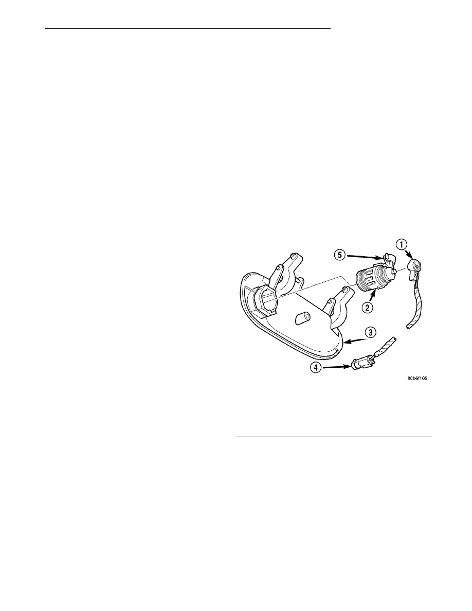
(3) Disconnect the wiring clip and pigtail wire con-

nector (Fig. 1).

(4) Remove the Door Cylinder Lock Switch from

door lock cylinder.

INSTALLATION

(1) Install the Door Cylinder Lock Switch onto the

door lock cylinder.

(2) Connect the wiring clip and pigtail wire con-

nector.

(3) Install door trim panel (Refer to 23 - BODY/

DOOR - FRONT/TRIM PANEL - INSTALLATION).

(4) Connect the battery negative cable.

Fig. 1 DOOR CYLINDER LOCK SWITCH

1 - DOOR CYLINDER LOCK SWITCH
2 - LOCK CYLINDER
3 - DOOR HANDLE
4 - PIGTAIL CONNECTOR
5 - CLIP

JR

POWER LOCKS

8N - 3

POWER LOCKS (Continued)

DOOR LOCK MOTOR

DIAGNOSIS AND TESTING - DOOR LOCK
MOTOR

Make certain battery is in normal condition before

circuits are tested.

To determine which motor is faulty, check each

individual door for electrical lock and unlock or dis-
connect the motor connectors one at a time, while
operating the door lock switch. In the event that
none of the motors work, the problem maybe caused
by a shorted motor, a bad switch, or a bad relay. Dis-
connecting a defective motor will allow the others to
work.

To test an individual door lock motor, disconnect

the electrical connector from the motor. To lock the
door, connect a 12 volt power source to the positive
pin of the lock motor and a ground wire to the other
pin. To unlock the door reverse the wire connections
at the motor pin terminals. If these results are NOT
obtained, replace the motor.

The door lock motor is integral to the door latch. If

faulty, the entire door latch must be replaced.

DOOR LOCK / UNLOCK
SWITCH

DIAGNOSIS AND TESTING - DOOR LOCK /
UNLOCK SWITCH

VOLTAGE

The following wiring test sequence determines

whether or not voltage is continuous through the
body harness to switch.

(1) Remove switch from door trim panel.
(2) Carefully separate multiple terminal block on

wiring harness from switch body.

(3) Connect one lead of test light to a ground ter-

minal:

• Touch other test light lead to battery feed B+

terminal.

• If test light comes on, the wiring circuit between

the battery and switch is functional.

• If test light does not come on, check fuse 13 in

the Junction Block for a blown fuse. Refer to Wiring
Diagrams for circuit information.

DOOR LOCK SWITCH

Remove the switch from its mounting location.

Using an ohmmeter, refer to the DOOR LOCK
SWITCH CONTINUITY table to determine if the
continuity is correct in the LOCK and UNLOCK
switch positions. If these results are not obtained,
replace the switch.

DOOR LOCK SWITCH CONTINUITY

SWITCH

POSITION

CONTINUITY

BETWEEN

RESISTANCE

VALUE

LOCK

1 AND 4

2700

V

± 10%

UNLOCK

1 AND 4

620

V

± 10%

REMOVAL

(1) Disconnect and isolate the battery negative

remote cable.

(2) Remove door trim panel (Refer to 23 - BODY/

DOOR - FRONT/TRIM PANEL - REMOVAL).

(3) Disconnect switch wire connector.
(4) Remove switch using a trim stick (special tool

#C-4755) or equivalent.

INSTALLATION

(1) Install the switch by snapping into place.
(2) Connect switch wire connector.
(3) Install the door trim panel (Refer to 23 -

BODY/DOOR - FRONT/TRIM PANEL - INSTALLA-
TION).

(4) Connect the battery negative remote cable.

DECKLID RELEASE SOLENOID

DIAGNOSIS AND TESTING - DECKLID RELEASE
SOLENOID

(1) Confirm motor lead wire is connected and 10

volts or more are available at solenoid.

(2) Provide proper ground through latch mounting

screws.

(3) Remove latch and examine plunger. Plunger

should spring back when pressed.

(4) Insure that solenoid plunger travel is adequate

approximately 16 mm (5/8 inch).

REMOVAL

(1) Disconnect and isolate the negative battery

cable remote terminal from the remote battery post.

(2) Raise deck lid to the full up position.
(3) Remove latch cover push pins then remove

cover.

(4) Remove two retaining nuts to latch and motor,

then remove latch and motor assembly.

INSTALLATION

(1) Install the latch and motor assembly. Install

the two retaining nuts.

(2) Install latch cover and push pins.
(3) Close the deck lid.
(4) Connect the negative battery cable remote ter-

minal to the remote battery post.

8N - 4

POWER LOCKS

JR

DECKLID RELEASE SWITCH

REMOVAL

(1) Disconnect and isolate the battery negative

cable.

(2) Remove left lower instrument panel cover.
(3) Disconnect the wire connector.
(4) Pinch four tabs around side of decklid release

switch on the rear side of the left lower instrument
panel trim, and push switch through opening.

INSTALLATION

(1) Position the decklid release switch over open-

ing of the left lower instrument panel trim, and push
switch through opening.

(2) Connect the wire connector.
(3) Install the left lower instrument panel cover.
(4) Connect the battery negative cable.

KEYLESS ENTRY
TRANSMITTER

DIAGNOSIS AND TESTING - KEYLESS ENTRY
MODULE

Using special tool 9001, first test to ensure that

the transmitter is functioning. Typical testing dis-
tance is 2.5 centimeters (1 inch) for Asian transmit-
ters and 30.5 centimeters (12 inches) for all others.
To test, position the transmitter as shown (Fig. 2).
Press any transmitter button, then test each button
individually. The tool will beep if a radio signal
strength that lights five or more LED’s is detected.
Repeat this test three times. If transmitter fails any
of the test refer to the Diagnostic Procedures man-
ual.

STANDARD PROCEDURE - RKE TRANSMITTER
PROGRAMMING

The Remote Keyless Entry (RKE) Transmitter(s)

can be programmed with the use of the DRB III

t

scan tool, or by the customer.

New Remote Keyless Entry (RKE) transmitters can

be programed using the DRBIII

t scan tool and the

proper Diagnostic Procedures manual, if no function-
ing transmitter is available. The DRBIII

t scan tool

can provide confirmation that the PCI data bus is
functional, and that all of the electronic modules are
sending and receiving the proper messages on the
PCI data bus.

The following procedure can be used as long as one

functioning transmitter is available:

(1) Turn ignition to the RUN position (allow igni-

tion chimes to stop).

(2) Using any original (working) transmitter, press

the UNLOCK button for 4 to 10 seconds.

(3) Within the specified 4 to 10 seconds, continue

pressing the UNLOCK button and press the PANIC
button for 1 second, and release both buttons. A
chime will sound to indicate that the transmitter pro-
gramming mode has been entered (allow 3 seconds
for chime to sound).

(4) Press LOCK and UNLOCK buttons simulta-

neously for 1 second and release.

(5) Press and release any button on the same

transmitter and a chime will sound after successfully
programming the transmitter.

(6) Repeat steps 5 and 6 to program additional

transmitters.

(7) Turn ignition to the OFF position. Transmitter

programming mode will discontinue after 60 seconds.
All transmitter programming must be completed
within time specified.

SPECIFICATIONS

TRANSMITTER

BATTERY

The transmitter has two 3 volt batteries, which can

be removed and replaced without special tools. Insert
a dime in the side slot of the transmitter and twist.
the halves should separate and the batteries are
stacked on top of each other. The batteries are avail-
able at local retail stores. Recommended batteries are
Panasonic CR 2016 or equivalent. Battery life is
about two years.

RANGE

Operation range is within 12 meters (40 ft.) of the

module/receiver.

Fig. 2 RKE TRANSMITTER DIAGNOSIS

JR

POWER LOCKS

8N - 5

REMOTE KEYLESS ENTRY
MODULE

REMOVAL

(1) Disconnect the remote battery negative cable

from the terminal on the shock tower.

The Junction Block and Body Control Module

(BCM) are attached to each other. After removal they
can be separated.

(2) Open the front driver’s door and remove end

cap.

(3) Remove instrument panel outboard bezel (Refer

to 23 - BODY/INSTRUMENT PANEL/INSTRUMENT
PANEL TRIM - REMOVAL).

(4) Remove instrument panel center bezel (Refer to

23 - BODY/INSTRUMENT PANEL/INSTRUMENT
PANEL CENTER BEZEL - REMOVAL).

(5) Remove instrument panel inboard bezel (Refer

to 23 - BODY/INSTRUMENT PANEL/INSTRUMENT
PANEL TRIM - REMOVAL).

(6) Remove the left lower instrument panel trim.
(7) Remove silencer.
(8) Remove wire harness connectors from Junction

Block.

(9) Remove Junction Block three mounting screws.
(10) Remove

Junction

Block/BCM

by

pulling

straight down from the mounting bayonet.

(11) Disconnect BCM wire connectors and remove

the assembly.

(12) Remove Junction Block/BCM from vehicle.
(13) With the Junction Block/BCM removed from

the vehicle, separate the BCM from the Junction
Block.

(14) Disconnect BCM from the Junction Block.
(15) Unsnap the remote keyless entry module from

the BCM.

NOTE: The Remote Keyless Entry (RKE) module is
attached to the BCM. This must be transferred (if
equipped) to the new BCM if being replaced.

NOTE: If BCM is replaced, the VTSS must be
enabled in the new BCM via the DRB lll

T

in order to

start the vehicle.

INSTALLATION

(1) Snap the remote keyless entry module onto the

BCM.

(2) Connect BCM to the Junction Block.
(3) Connect the BCM and junction block together.
(4) Install the Junction Block/BCM into vehicle.
(5) Connect BCM wire connectors and install the

assembly onto instrument panel.

(6) Install the Junction Block/BCM by pushing

straight up.

(7) Install the Junction Block three mounting

screws.

(8) Install the wire harness connectors to the Junc-

tion Block.

(9) Install the silencer.
(10) Install the left lower instrument panel trim.
(11) Install the instrument panel inboard bezel

(Refer to 23 - BODY/INSTRUMENT PANEL/IN-
STRUMENT PANEL TRIM - INSTALLATION).

(12) Install the instrument panel center bezel

(Refer to 23 - BODY/INSTRUMENT PANEL/IN-
STRUMENT PANEL CENTER BEZEL - INSTALLA-
TION).

(13) Install the instrument panel outboard bezel

(Refer to 23 - BODY/INSTRUMENT PANEL/IN-
STRUMENT PANEL TRIM - INSTALLATION).

(14) Install the left end cover.
(15) Connect the remote battery negative cable to

the remote terminal on the shock tower.

8N - 6

POWER LOCKS

JR


Content   ..  338  339  340  341   ..