Chrysler Sebring, Stratus sedan, Sebring Convertible. Manual - part 339


  Index      Chrysler     Chrysler Sebring, Stratus sedan, Sebring Convertible - service repair manual 2001-2007 year


Search            


Content   ..  337  338  339  340   ..


Chrysler Sebring, Stratus sedan, Sebring Convertible. Manual - part 339


UNIVERSAL TRANSMITTER

TABLE OF CONTENTS

page

page

UNIVERSAL TRANSMITTER

DESCRIPTION

. . . . . . . . . . . . . . . . . . . . . . . . . . 5

OPERATION

. . . . . . . . . . . . . . . . . . . . . . . . . . . . 5

DIAGNOSIS AND TESTING - UNIVERSAL

TRANSMITTER

. . . . . . . . . . . . . . . . . . . . . . . . 5

REMOVAL

. . . . . . . . . . . . . . . . . . . . . . . . . . . . . 5

UNIVERSAL TRANSMITTER

DESCRIPTION

Some JR models are equipped with a Universal

Transmitter transceiver as standard factory-installed
equipment. The universal transmitter transceiver is
located in the drivers side sun visor assembly. The
only visible component of the universal transmitter
are the three transmitter push buttons. The three
universal transmitter push buttons are identified
with raised buttons and light indicators so that they
can be easily identified by sight or by feel.

Each of the three universal transmitter push but-

tons controls an independent radio transmitter chan-
nel. Each of these three channels can be trained to
transmit a different radio frequency signal for the
remote operation of garage door openers, motorized
gate openers, home or office lighting, security sys-
tems or just about any other device that can be
equipped with a radio receiver in the 286 to 399
MegaHertz (MHz) frequency range for remote opera-
tion. The universal transmitter is capable of operat-
ing systems using either rolling code or non-rolling
code technology.

The universal transmitter cannot be repaired, and

is available for service only as a unit. If any part of
the component is faulty or damaged, the complete
assembly must be replaced.

OPERATION

The universal transmitter operates on a non-

switched source of battery current so the unit will
remain functional, regardless of the ignition switch
position. For more information on the features, pro-
gramming procedures and operation of the universal
transmitter, see the owner’s manual in the vehicle
glove box.

DIAGNOSIS AND TESTING - UNIVERSAL
TRANSMITTER

If the Universal Transmitter is inoperative, see the

owner’s manual in the vehicle glove box for instruc-
tions on training the universal transmitter. Retrain
the universal transmitter with a known good trans-
mitter as instructed in the owner’s manual and test

the universal transmitter operation again. If the unit
is still inoperative, test the universal transmitter
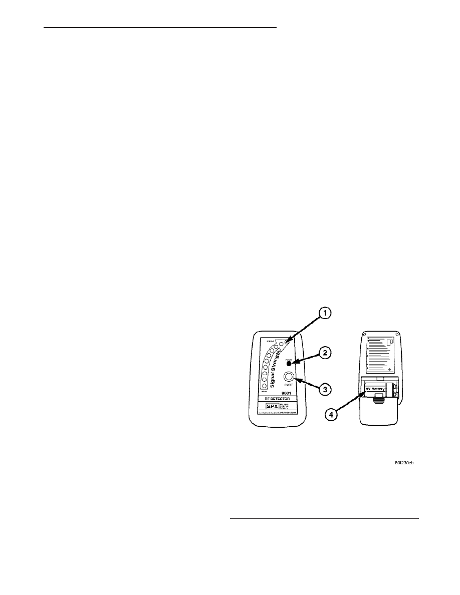
with Radio Frequency Detector special tool (Fig. 1) as
described below:

(1) Turn the Radio Frequency (RF) Detector ON. A

“chirp” will sound and the green power LED will
light. If the green LED does not light, replace the
battery.

(2) Hold the RF detector within one inch of the

TRAINED universal transmitter and press any of the
transmitters buttons.

(3) The red signal detection LEDs will light and

the tool will beep if a radio signal is detected. Repeat
this test three times.

REMOVAL

(1) For universal transmitter removal, Refer to 23

- BODY/INTERIOR/SUN VISOR - REMOVAL.

Fig. 1 Radio Frequency Detector

1 - SIGNAL DETECTION LED’S
2 - POWER LED
3 - ON/OFF SWITCH
4 - 9V BATTERY

JR

UNIVERSAL TRANSMITTER

8M - 5

POWER SYSTEMS

TABLE OF CONTENTS

page

page

POWER LOCKS . . . . . . . . . . . . . . . . . . . . . . . . . . . . 1
POWER MIRRORS . . . . . . . . . . . . . . . . . . . . . . . . . 7
POWER SEAT SYSTEM. . . . . . . . . . . . . . . . . . . . . 10

POWER TOP - CONVERTIBLE . . . . . . . . . . . . . . . 16
POWER TOP - SUNROOF . . . . . . . . . . . . . . . . . . . 21
POWER WINDOWS. . . . . . . . . . . . . . . . . . . . . . . . 28

POWER LOCKS

TABLE OF CONTENTS

page

page

POWER LOCKS

DESCRIPTION

. . . . . . . . . . . . . . . . . . . . . . . . . . 1

OPERATION

. . . . . . . . . . . . . . . . . . . . . . . . . . . . 2

DIAGNOSIS AND TESTING - REMOTE

KEYLESS ENTRY

. . . . . . . . . . . . . . . . . . . . . . 3

DOOR CYLINDER LOCK SWITCH

REMOVAL

. . . . . . . . . . . . . . . . . . . . . . . . . . . . . 3

INSTALLATION

. . . . . . . . . . . . . . . . . . . . . . . . . . 3

DOOR LOCK MOTOR

DIAGNOSIS AND TESTING - DOOR LOCK

MOTOR

. . . . . . . . . . . . . . . . . . . . . . . . . . . . . . 4

DOOR LOCK / UNLOCK SWITCH

DIAGNOSIS AND TESTING - DOOR LOCK /

UNLOCK SWITCH

. . . . . . . . . . . . . . . . . . . . . . 4

REMOVAL

. . . . . . . . . . . . . . . . . . . . . . . . . . . . . 4

INSTALLATION

. . . . . . . . . . . . . . . . . . . . . . . . . . 4

DECKLID RELEASE SOLENOID

DIAGNOSIS AND TESTING - DECKLID

RELEASE SOLENOID

. . . . . . . . . . . . . . . . . . . 4

REMOVAL

. . . . . . . . . . . . . . . . . . . . . . . . . . . . . 4

INSTALLATION

. . . . . . . . . . . . . . . . . . . . . . . . . . 4

DECKLID RELEASE SWITCH

REMOVAL

. . . . . . . . . . . . . . . . . . . . . . . . . . . . . 5

INSTALLATION

. . . . . . . . . . . . . . . . . . . . . . . . . . 5

KEYLESS ENTRY TRANSMITTER

DIAGNOSIS AND TESTING - KEYLESS ENTRY

MODULE

. . . . . . . . . . . . . . . . . . . . . . . . . . . . . 5

STANDARD PROCEDURE - RKE

TRANSMITTER PROGRAMMING

. . . . . . . . . . . 5

SPECIFICATIONS

TRANSMITTER

. . . . . . . . . . . . . . . . . . . . . . . . 5

REMOTE KEYLESS ENTRY MODULE

REMOVAL

. . . . . . . . . . . . . . . . . . . . . . . . . . . . . 6

INSTALLATION

. . . . . . . . . . . . . . . . . . . . . . . . . . 6

POWER LOCKS

DESCRIPTION

POWER DOOR LOCKS

The power lock system allows all doors to be locked

or unlocked electrically by operating the switch on
either front door trim panel. The power lock system
operates on non-switched battery current supplied
through a fuse in the junction block so that the sys-
tem remains functional, regardless of the ignition
switch position.

AUTOMATIC DOOR LOCKS

The system includes an automatic door locking fea-

ture actuated by the Body Control Module (BCM).
The vehicle is built with the system enabled.
The system can be enabled/disabled by the customer.
Refer to the owner’s manual for information.

The BCM will automatically lock all doors when all

of the conditions below are met:

• All doors are closed

• The vehicle speed exceeds 15 ± 1 M.P.H.

• The throttle position sensor tip-in is greater

than 10 ± 2 degrees

When the system is disabled the door locks will

work by use of the door lock switches only. When this

JR

POWER SYSTEMS

8N - 1

system is enabled the automatic door locks will work
automatically.

Auto unlock on exit is a feature which, when

enabled, automatically unlocks all doors upon the
ignition switch being turned off and the opening of
the driver’s door. Auto unlock on exit is only operable
when the automatic door locks are enabled.

CENTRAL LOCKING

The central locking system is part of the Vehicle

Theft Security System. This feature allows the doors
to be locked/unlocked all at once with the turn of the
key in the drivers door.

CHILD PROTECTION LOCK

The child protection locks are on the rear doors

only. When enabled, they render the inside remote
door release handles inoperative.

DOOR LOCK INHIBIT

The door lock inhibit feature is designed to prevent

the locking of keys in a vehicle. The drivers door can-
not be locked unless the keys are removed from the
ignition switch.

REMOTE KEYLESS ENTRY

The system allows locking and unlocking of vehicle

door(s), deck lid release, and panic by remote control
using a hand held radio frequency transmitter. The
vehicle must be in PARK before the trunk lid can be
unlatched with the transmitter.

The receiver may receive signals from up to four

transmitters. Each transmitter has its own code, and
the code is programmed and stored into receiver
memory. If a transmitter is replaced or additional
transmitters are added, the codes for all units have
to be reprogrammed into the receiver memory. If a
receiver module is replaced, the transmitter codes
must be stored in the new receiver memory.

HORN CHIRP TOGGLE

Once the transmitters have been programmed, the

horn chirp can be enabled/disabled by sending the
horn chirp toggle operation code to the Body Control
Module (BCM).

OPERATION

POWER DOOR LOCKS

All doors can be locked or unlocked electrically by

operating the switch on either front door panel.

The rear doors can be locked or unlocked by actu-

ation of the front door switch, or can be locked or
unlocked mechanically and independently with their
respective locking knobs.

The front doors can be locked or unlocked mechan-

ically with the locking knob regardless of electrical
locking and unlocking actuation with the front door
knobs.

The right and left front door on all vehicles can be

locked or unlocked mechanically from the outside
with the key or electrically as described above. The
left and right front doors can also be unlocked by
actuation of the inside remote door handle.

AUTOMATIC DOOR LOCKS

The BCM controls the power locks when the door

lock switch is activated. If the door lock switch is
pressed for longer than eight consecutive seconds, the
BCM will de-energize the door lock relay.

The automatic door lock system can be enabled/dis-

abled either by the customer or with the DRB III

t

scan tool. Refer to the DRB III

t or the vehicle own-

ers manual for enabling/disabling procedures.

The BCM will automatically re-lock all doors if the

above conditions are met and if any of the doors
become ajar and then closes again.

The power latches are also equipped with a ther-

mal protection system which prevents the latches
from burning out.

CENTRAL LOCKING

Using the key, turn the driver’s door cylinder lock

to the lock position, all doors will lock. This feature
operates differently on each door. Turn key in the
driver’s door to the unlock position once will unlock
driver’s door only. Turning the key a second time to
the unlock position within five seconds of the first
time will unlock all doors.

The lock/unlock operation will arm/disarm the

Vehicle Theft Security System and will also activate/
cancel the illuminated entry feature.

CHILD PROTECTION LOCK

The lock when engaged, will disable the inside door

handle from opening the door. The lock is part of the
latch/lock assembly. The lock is engaged by moving a
lever that is located on the rearward inside edge of
the door.

DOOR LOCK INHIBIT

With the key in the ignition switch in the ON or

OFF position and the driver’s door open the BCM
will ignore the command to lock the power door
locks. Once the key is removed, or the driver’s door is
closed, the body control module will allow the power
door locks to lock.

8N - 2

POWER LOCKS

JR

POWER LOCKS (Continued)


Content   ..  337  338  339  340   ..