Chrysler Sebring, Stratus sedan, Sebring Convertible. Manual - part 301


  Index      Chrysler     Chrysler Sebring, Stratus sedan, Sebring Convertible - service repair manual 2001-2007 year


Search            


Content   ..  299  300  301  302   ..


Chrysler Sebring, Stratus sedan, Sebring Convertible. Manual - part 301


REMOVAL

(1) Remove the transaxle from the vehicle. (Refer

to 21 - TRANSMISSION/TRANSAXLE/T350 MAN-
UAL - REMOVAL)

(2) Move the lever and bearing assembly (Fig. 9) to

a vertical in-line position. Grasp the release lever
with two hands in the pivot stud socket area. Pull
with even pressure and the lever will pop off the piv-
ot–stud. Do not use a screwdriver or pry bar to pop
off the lever. This may damage the spring clip on the
lever.

(3) As a unit, remove the lever from the bearing

thrust plate. Be careful not to damage retention tabs
on bearing.

(4) Examine the condition of the bearing. It is

pre-lubricated and sealed and should not be
immersed in oil or solvent.

(5) The bearing should turn smoothly when held in

the hand under a light thrust load. A light drag
caused by the lubricant fill is normal. If the bearing
is noisy, rough, or dry, replace the complete bearing
assembly with a new bearing.

(6) Check the condition of the pivot stud spring

clips on the back side of the clutch release lever. If
the clips are broken or distorted, replace the release
lever.

NOTE: Remove release lever pivot ball only if
replacement is necessary.

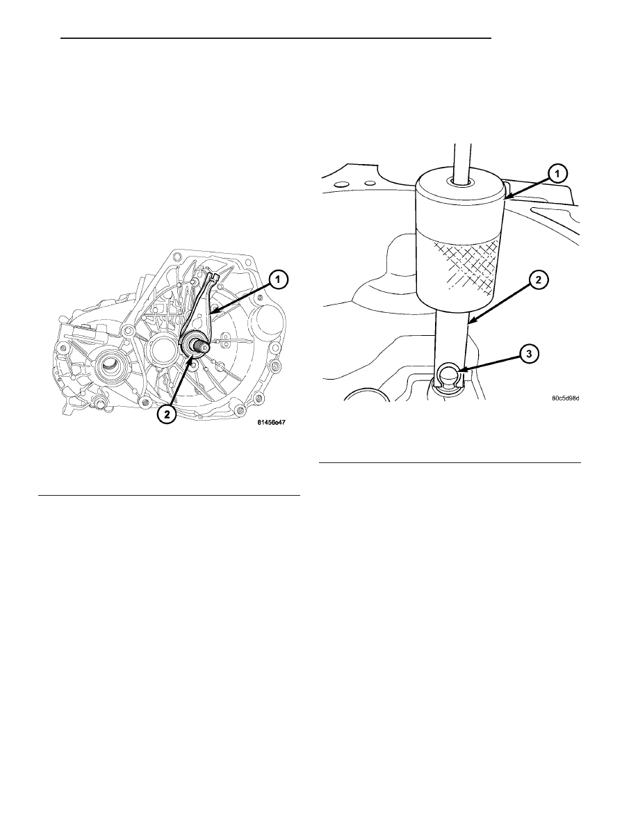
(7) Remove pivot ball using slide hammer C-3752

and remover/installer 6891 (Fig. 10).

INSTALLATION

(1) If removed, install new release lever pivot

ball(s) using slide hammer C-3752 and remover/in-
staller 6891 (Fig. 10).

(2) The pivot ball pocket in the lever, as well as

the lever arms should be lubricated with grease prior
to installation.

(3) Assemble the lever to the bearing. The small

pegs on the bearing must go over the lever arms.

(4) Slide the bearing and lever assembly onto the

input shaft bearing retainer, as a unit (Fig. 9).

(5) Snap the clutch release lever onto the pivot

ball.

(6) Reinstall transaxle assembly. (Refer to 21 -

TRANSMISSION/TRANSAXLE/T350

MANUAL

-

INSTALLATION)

Fig. 9 Clutch Release Lever and Bearing

1 - LEVER
2 - BEARING

Fig. 10 Pivot Ball Removal/Installation

1 - C-3752 SLIDE HAMMER
2 - REMOVER/INSTALLER 6891
3 - PIVOT BALL

JR

CLUTCH

6 - 9

CLUTCH RELEASE BEARING AND LEVER (Continued)

CLUTCH RELEASE CABLE

DESCRIPTION

2.0L equipped models use a cable style clutch

release system. The clutch cable assembly (Fig. 11)
carries the movement of the clutch pedal to the
clutch release bearing. The cable is designed to main-
tain tension against the clutch fork, or lever, and has
a built in self-adjusting mechanism, which compen-
sates for clutch disc wear.

REMOVAL

(1) Disconnect battery negative cable.
(2) Remove air cleaner assembly.
(3) Remove bellhousing cap (Fig. 12).
(4) Disconnect clutch cable from release lever (Fig.

12).

(5) Remove steering column lower shroud.
(6) Remove knee bolster.
(7) Remove upstop spacer retainer clip from pedal

pin.

NOTE: Depressing the clutch pedal provides access
to the clutch cable strand. Disconnect the cable up-
stop/spacer from the pedal pivot pin by removing
the retaining clip at the top of the clutch pedal.
Wedge a flat–blade pry tool between the pin and the
retaining tab. While holding the tab slightly sepa-
rated from the pin, pull the upstop/spacer off the
pedal. Now remove the cable end from the upstop/
spacer.

(8) Remove clutch release cable core from upstop

spacer (Fig. 13).

(9) Loosen but do not remove four (4) brake boost-

er-to-dash panel nuts.

(10) Remove clutch release cable through engine

compartment.

INSTALLATION

(1) Feed clutch release cable through dash panel

hole and into passenger compartment.

Fig. 11 Clutch Cable Assembly

1 - ADJUSTER MECHANISM
2 - CLUTCH CABLE

Fig. 12 Clutch Cable at Transaxle

1 - CLUTCH CABLE
2 - TRANSAXLE
3 - BELLHOUSING CAP

Fig. 13 Clutch Cable at Pedal Assembly

1 - CABLE ASSEMBLY
2 - CLUTCH PEDAL
3 - SPACER
4 - CABLE CORE

6 - 10

CLUTCH

JR

(2) Connect clutch release cable core to upstop

spacer.

(3) Connect upstop spacer to clutch pedal pin and

secure with retainer clip.

(4) Route clutch release cable through engine com-

partment as removed, and connect clutch release
cable to clutch release lever (Fig. 12).

(5) Verify adjuster mechanism operation: With

slight pressure, pull the clutch release lever end of
the cable to draw the cable taut. Push the clutch
cable housing toward the dash panel (With less than
25 lbs. of effort, the cable housing should move
30-50mm.). This indicates proper adjuster mecha-
nism function. If the cable does not adjust, determine
if the mechanism is properly seated on the bracket.

(6) Install bellhousing cap (Fig. 12).
(7) Torque brake booster nuts.
(8) Install knee bolster.
(9) Install steering column lower shroud.
(10) Install air cleaner assembly.
(11) Connect battery negative cable.

MODULAR CLUTCH

DESCRIPTION

Manual transaxle equipped vehicles utilize a mod-

ular clutch assembly (Fig. 14). The transaxle must be
removed to gain access to and replace the modular
clutch, drive plate, and/or clutch release bearing and
lever.

The modular clutch assembly used in this vehicle

consists of a single, dry-type clutch disc, a diaphragm
style clutch cover, and an integrated flywheel. The
clutch cover is riveted to the flywheel, containing the
clutch disc within. The modular clutch can only be
serviced as an assembly.

The clutch disc has cushion springs riveted to the

disc hub assembly. The clutch disc facings are riveted
to the cushion springs. The facings are made from a
non-asbestos material.

The clutch cover pressure plate assembly is a dia-

phragm type unit with a one-piece diaphragm spring
with multiple release fingers. The pressure plate
release fingers are preset during manufacture and
are not adjustable.

REMOVAL

(1) Remove transaxle and modular clutch assembly

from engine. (Refer to 21 - TRANSMISSION/TRANS-
AXLE/MANUAL - REMOVAL)

(2) Remove the modular clutch assembly fom the

transaxle input shaft (Fig. 15).

INSTALLATION

(1) Install modular clutch assembly onto input

shaft (Fig. 15).

(2) Install transaxle to vehicle. (Refer to 21 -

TRANSMISSION/TRANSAXLE/MANUAL - INSTAL-
LATION)

Fig. 14 Modular Clutch Assembly

1 - MODULAR CLUTCH ASSEMBLY

JR

CLUTCH

6 - 11

CLUTCH RELEASE CABLE (Continued)

Fig. 15 Modular Clutch Removal/Installation

1 - MODULAR CLUTCH ASSEMBLY
2 - CLIP

3 - TRANSAXLE
4 - CLUTCH MODULE BOLT (4)

6 - 12

CLUTCH

JR

MODULAR CLUTCH (Continued)


Content   ..  299  300  301  302   ..