Chrysler RG Voyager. Manual - part 963


  Index      Chrysler     Chrysler RG Voyager - service repair manual 2005 year


Search            


Content   ..  961  962  963  964   ..


Chrysler RG Voyager. Manual - part 963


(14) Connect the heater return hose at rear of tim-

ing chain cover (Fig. 138) or at water pump inlet
tube (if engine oil cooler equipped) (Fig. 139).

(15) Connect the radiator lower hose.
(16) Install A/C compressor.
(17) Install accessory drive belt. (Refer to 7 -

COOLING/ACCESSORY

DRIVE/DRIVE

BELTS

-

INSTALLATION)

(18) Install oil pump pick-up tube with new

O-ring. Tighten attaching bolt to 28 N·m (250 in.
lbs.).

(19) Install oil pan. (Refer to 9 - ENGINE/LUBRI-

CATION/OIL PAN - INSTALLATION)

(20) Install inner splash shield and right front

wheel.

(21) Fill crankcase with engine oil to proper level.
(22) Fill cooling system. (Refer to 7 - COOLING -

STANDARD PROCEDURE)

(23) Connect negative cable to battery.

TIMING CHAIN AND
SPROCKETS

REMOVAL

REMOVAL - TIMING CHAIN AND CAMSHAFT
SPROCKET

(1) Disconnect negative cable from battery.
(2) Remove the timing chain cover. (Refer to 9 -

ENGINE/VALVE TIMING/TIMING BELT / CHAIN
COVER(S) - REMOVAL)

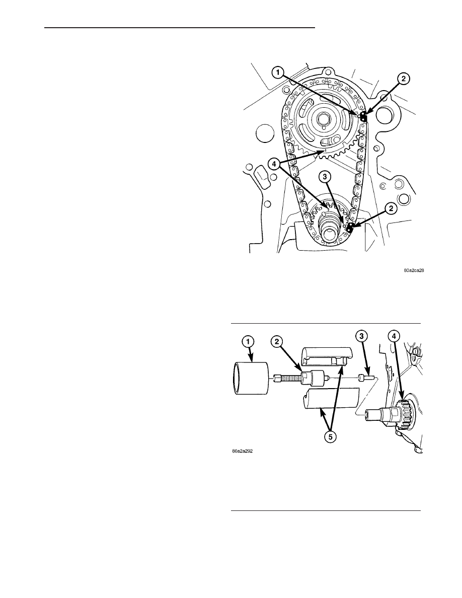
(3) Rotate engine by turning crankshaft until the

timing marks are aligned as shown in (Fig. 144).

(4) Remove camshaft sprocket attaching bolt.
(5) Remove

the

timing

chain

with

camshaft

sprocket.

(6) Remove the crankshaft sprocket. (Refer to 9 -

ENGINE/VALVE

TIMING/TIMING

BELT/CHAIN

AND SPROCKETS - REMOVAL)

REMOVAL - CRANKSHAFT SPROCKET

(1) Remove

the

timing

chain.

(Refer

to

9

-

ENGINE/VALVE

TIMING/TIMING

BELT/CHAIN

AND SPROCKETS - REMOVAL)

(2) Using Special Tools 8539, 5048-6, and 5048-1,

remove the crankshaft sprocket while holding the
crankshaft from turning (Fig. 145). Be careful not to
damage the crankshaft surfaces.

Fig. 144 Timing Mark Alignment

1 - CAMSHAFT SPROCKET TIMING MARK (DOT)
2 - PLATED LINK
3 - CRANKSHAFT SPROCKET TIMING MARK (DOT)
4 - ARROWS

Fig. 145 CRANKSHAFT SPROCKET - REMOVAL

1 - SPECIAL TOOL 5048-6
2 - SPECIAL TOOL 5048-1
3 - SPECIAL TOOL 8450
4 - CRANKSHAFT SPROCKET
5 - SPECIAL TOOL 8539

RS

ENGINE 3.3/3.8L

9 - 161

TIMING CHAIN COVER (Continued)

INSTALLATION

INSTALLATION - CRANKSHAFT SPROCKET

(1) Position the sprocket on the crankshaft (timing

mark out) with the timing slot aligned with the tim-
ing pin.

(2) Install sprocket using Special Tool 8452 (Fig.

146). Install sprocket until it is fully seats on the
crankshaft.

(3) Install the timing chain and camshaft sprocket.

(Refer to 9 - ENGINE/VALVE TIMING/TIMING
BELT/CHAIN AND SPROCKETS - INSTALLATION)

INSTALLATION - TIMING CHAIN AND
CAMSHAFT SPROCKET

(1) Rotate crankshaft so the timing arrow is to the

12 o’clock position (Fig. 144).

NOTE: Lubricate timing chain and sprockets with
clean engine oil before installation.

(2) While holding camshaft sprocket and chain in

hand, place timing chain around the sprocket, align-
ing the plated link with the dot on the sprocket. Posi-
tion the timing arrow to the 6 o’clock position (Fig.
144).

(3) Place timing chain around crankshaft sprocket

with the plated link lined up with the dot on the
sprocket. Install camshaft sprocket into position.

(4) Use a straight edge to check alignment of tim-

ing marks.

(5) Install camshaft sprocket bolt and washer.

Tighten bolt to 54 N·m (40 ft. lbs.).

(6) Rotate crankshaft 2 revolutions and check tim-

ing mark alignment (Fig. 144). If timing marks do
not line up, remove camshaft sprocket and realign.

(7) Install the timing chain cover. (Refer to 9 -

ENGINE/VALVE TIMING/TIMING BELT / CHAIN
COVER(S) - INSTALLATION)

(8) Connect negative cable to battery.

Fig. 146 CRANKSHAFT SPROCKET - INSTALLATION

1 - SPECIAL TOOL 8452-3
2 - SPECIAL TOOL 8452-1
3 - CRANKSHAFT SPROCKET
4 - THRUST BEARING / WASHER

9 - 162

ENGINE 3.3/3.8L

RS

TIMING CHAIN AND SPROCKETS (Continued)

EXHAUST SYSTEM

TABLE OF CONTENTS

page

page

EXHAUST SYSTEM

DESCRIPTION

. . . . . . . . . . . . . . . . . . . . . . . . . . 1

DIAGNOSIS AND TESTING

DIAGNOSIS AND TESTING - EXCESSIVE

EXHAUST SYSTEM NOISE . . . . . . . . . . . . . . . 2

DIAGNOSIS AND TESTING - EXHAUST

SYSTEM RESTRICTION CHECK . . . . . . . . . . . 3

INSPECTION

. . . . . . . . . . . . . . . . . . . . . . . . . . . 3

ADJUSTMENTS

. . . . . . . . . . . . . . . . . . . . . . . . . 3

SPECIFICATIONS

TORQUE

. . . . . . . . . . . . . . . . . . . . . . . . . . . . . 4

SPECIAL TOOLS

EXHAUST SYSTEM

. . . . . . . . . . . . . . . . . . . . . 4

CATALYTIC CONVERTER

DESCRIPTION

. . . . . . . . . . . . . . . . . . . . . . . . . . 4

OPERATION

. . . . . . . . . . . . . . . . . . . . . . . . . . . . 5

REMOVAL

. . . . . . . . . . . . . . . . . . . . . . . . . . . . . 5

INSPECTION

. . . . . . . . . . . . . . . . . . . . . . . . . . . 5

INSTALLATION

. . . . . . . . . . . . . . . . . . . . . . . . . . 6

CROSS-OVER PIPE - 3.3/3.8L

REMOVAL

. . . . . . . . . . . . . . . . . . . . . . . . . . . . . 6

INSTALLATION

. . . . . . . . . . . . . . . . . . . . . . . . . . 6

HEAT SHIELDS

DESCRIPTION

. . . . . . . . . . . . . . . . . . . . . . . . . . 7

OPERATION

. . . . . . . . . . . . . . . . . . . . . . . . . . . . 7

REMOVAL

. . . . . . . . . . . . . . . . . . . . . . . . . . . . . 8

INSTALLATION

. . . . . . . . . . . . . . . . . . . . . . . . . . 8

MUFFLER

REMOVAL

. . . . . . . . . . . . . . . . . . . . . . . . . . . . . 8

INSTALLATION

. . . . . . . . . . . . . . . . . . . . . . . . . . 8

RESONATOR

REMOVAL

. . . . . . . . . . . . . . . . . . . . . . . . . . . . . 9

INSTALLATION

. . . . . . . . . . . . . . . . . . . . . . . . . . 9

EXHAUST SYSTEM

DESCRIPTION

The exhaust system consists of a catalytic con-

verter, muffler, and a resonator with connecting pipes
in-between (Fig. 1). The system is serviced in two
sections; the catalytic converter and pipe, and the
muffler and resonator with connecting pipe. A band
clamp is used to connect the joint between the two
components. Three support hanger rods with rubber
isolators are used to support and isolate the exhaust
system. A flexible joint, integral to the catalytic con-
verter, allows for engine movement. On vehicles
equipped with AWD, an additional heat shield is
mounted to the catalytic converter. The exhaust sys-
tem is tuned for each vehicle/powertrain combination.

RS

EXHAUST SYSTEM

11 - 1

DIAGNOSIS AND TESTING

DIAGNOSIS AND TESTING - EXCESSIVE
EXHAUST SYSTEM NOISE

CONDITION

POSSIBLE CAUSES

CORRECTION

EXCESSIVE EXHAUST NOISE
(UNDER HOOD)

1. Exhaust manifold cracked or
broken.

1. Replace manifold.

2. Manifold to cylinder head leak.

2. Tighten manifold and/or replace
gasket.

3. EGR Valve to manifold gasket
leakage.

3. Tighten fasteners or replace
gasket.

4. EGR Valve to EGR tube gasket
leakage.

4. Tighten fasteners or replace
gasket.

5. EGR tube to manifold tube
leakage.

5. Tighten tube nut.

6. Exhaust flex-joint to manifold
leak.

6. Tighten joint fasteners and/or
replace gasket.

7. Exhaust flex-joint.

7. Replace catalytic converter
assembly.

8. Pipe and shell noise from front
exhaust pipe.

8. Characteristic of single wall pipe.

Fig. 1 Exhaust System - Typical (All Vehicles)

1 - CATALYTIC CONVERTER

4 - SUPPORT - RESONATOR

2 - BAND CLAMP

5 - RESONATOR

3 - SUPPORTS - MUFFLER

6 - MUFFLER

11 - 2

EXHAUST SYSTEM

RS

EXHAUST SYSTEM (Continued)


Content   ..  961  962  963  964   ..