Chrysler RG Voyager. Manual - part 675


  Index      Chrysler     Chrysler RG Voyager - service repair manual 2005 year


Search            


Content   ..  673  674  675  676   ..


Chrysler RG Voyager. Manual - part 675


CHANICAL/ICU (INTEGRATED CONTROL UNIT) -
DISASSEMBLY).

DISASSEMBLY

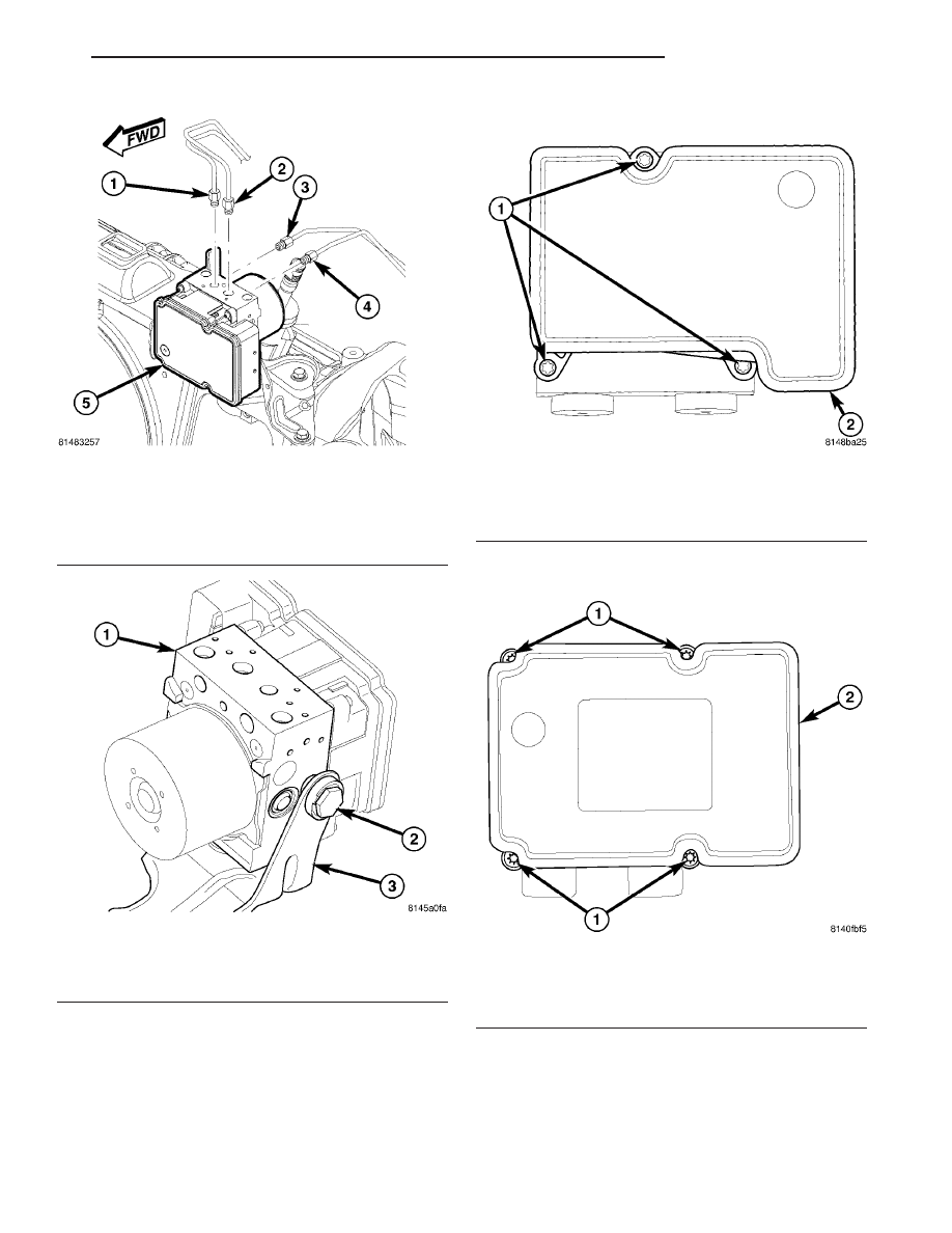
(1) If not equipped with traction control, remove

the three screws attaching the ABM to the HCU (Fig.
39).

(2) If equipped with traction control, remove the

four screws attaching the ABM to the HCU (Fig. 40).

(3) Separate the ABM from the HCU (Fig. 41).

Fig. 37 Chassis Brake Tubes At ICU

1 - RIGHT FRONT CHASSIS BRAKE TUBE
2 - LEFT FRONT CHASSIS BRAKE TUBE
3 - LEFT REAR CHASSIS BRAKE TUBE
4 - RIGHT REAR CHASSIS BRAKE TUBE
5 - ICU

Fig. 38 ICU Mounting Bolt

1 - ICU
2 - MOUNTING BOLT
3 - MOUNTING BRACKET

Fig. 39 ABM Mounting Screws - Without Traction

Control

1 - MOUNTING SCREWS
2 - ABM

Fig. 40 ABM Mounting Screws - With Traction

Control

1 - MOUNTING SCREWS
2 - ABM

RS

BRAKES - ABS

5 - 113

INTEGRATED CONTROL UNIT (ICU) - MK25E (Continued)

ASSEMBLY

(1) Clean any debris off the mating surfaces of the

HCU and ABM.

CAUTION: When installing new O-rings or solenoid
valve stem seals, do not use any type of lubricant.

(2) If the seals on the components are not new,

they must be replaced. Each of the solenoid valve
stem seals must be replaced (Fig. 42); do not reuse
solenoid valve stem seals
. The pump/motor con-
nector O-ring should also be replaced if not new (Fig.
43).

(3) Align components and install the ABM on the

HCU (Fig. 41).

(4) If not equipped with traction control, install

the three screws attaching the ABM to the HCU (Fig.
39). Tighten the mounting screws to 2 N·m (17 in.
lbs.) torque.

(5) If equipped with traction control, install the

four screws attaching the ABM to the HCU (Fig. 40).
Tighten the mounting screws to 2 N·m (17 in. lbs.)
torque.

(6) Install the ICU in the vehicle. (Refer to 5 -

BRAKES/HYDRAULIC/MECHANICAL/ICU

(INTE-

GRATED CONTROL UNIT) - INSTALLATION)

INSTALLATION

(1) Place the ICU in its bracket below the master

cylinder by first inserting the mounting pins on the
bottom of the ICU into the grommets mounted in the
bracket, then install the single mounting bolt on the

side (Fig. 38). Tighten the mounting bolt to 11 N·m
(97 in. lbs.) torque.

(2) Install the four chassis brake tubes into their

correct port locations on the ICU as shown (Fig. 37).
Tighten the tube nuts to a torque of 17 N·m (145 in.
lbs.).

Fig. 41 ABM Assembly To HCU

1 - ABM
2 - HCU
3 - SOLENOID VALVE STEM

Fig. 42 Solenoid Valve Seal

1 - SEAL
2 - SOLENOID VALVE STEM

Fig. 43 Internal Pump Connector O-Ring

1 - O-RING
2 - O-RING MOUNTING GROOVE

5 - 114

BRAKES - ABS

RS

INTEGRATED CONTROL UNIT (ICU) - MK25E (Continued)

CAUTION: Because of the flexible section in the pri-
mary and secondary brake tubes, the brake tubes
must be held in proper orientation when tightened
and torqued. These tubes must not contact each
other or other vehicle components when installed.
Also, after the brake tubes are installed on the ICU,
ensure all spacer clips are reinstalled on the brake
tubes.

(3) Install the primary and secondary brake tubes

into their correct port locations on the ICU (Fig. 36).
Tighten the tube nuts to a torque of 17 N·m (145 in.
lbs.).

(4) Install any routing clips on the brake tubes.
(5) With connector cover completely open (Fig. 35),

install 47-way wiring connector into socket of the
ABM and close cover, locking connector in place.

(6) Install the speed control servo with its mount-

ing nuts.

(7) Connect the wiring harness to the speed con-

trol servo.

(8) Install the battery tray. (Refer to 8 - ELECTRI-

CAL/BATTERY SYSTEM/TRAY - INSTALLATION)

(9) Install the screw securing the coolant filler

neck to the battery tray.

(10) Reconnect the vacuum hose connector at the

tank built into the battery tray.

(11) Install the battery and battery shield. (Refer

to 8 - ELECTRICAL/BATTERY SYSTEM/BATTERY -
INSTALLATION)

(12) Remove the brake pedal holder.
(13) Connect the negative cable on the battery

negative post.

(14) Hook up a scan tool to initialize ABM and

check for any faults.

(15) Fill master cylinder with clean, fresh Mopar

t

Brake Fluid or equivalent, then bleed base brakes
and ABS. (Refer to 5 - BRAKES - STANDARD PRO-
CEDURE)

(16) Road test vehicle to ensure proper operation

of brakes.

RS

BRAKES - ABS

5 - 115

INTEGRATED CONTROL UNIT (ICU) - MK25E (Continued)


Content   ..  673  674  675  676   ..