Chrysler RG Voyager. Manual - part 244
TEST
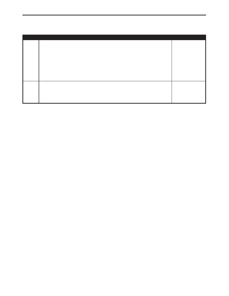
ACTION
APPLICABILITY
3
Disconnect the Right Cylinder Lock Switch connector.
Disconnect the Body Control Module C3 connector.
Measure the resistance between Cylinder Lock Switch Mux circuit and ground.
Is the resistance below 1000.0 ohms?
All
Yes
→ Repair the Cylinder Lock Switch Mux circuit for a short to
ground.
Perform BODY VERIFICATION TEST - VER 1.
No
→ Go To 4
4
If there are no possible causes remaining, view repair.
All
Repair
Replace the Body Control Module.
Perform BODY VERIFICATION TEST - VER 1.
945
POWER DOOR LOCKS/RKE
RIGHT CYLINDER LOCK SWITCH INPUT SHORT - BCM (EXPORT ONLY
- IF EQUIPPED) —
Continued