Chrysler PT Cruiser. Manual - part 840
INSTALLATION
NOTE: To ease installation of the valve body, turn
the manual valve lever fully clockwise.
(1) Install overdrive and underdrive accumulators
and springs as previously removed (Fig. 383).
(2) Guide park rod rollers into guide bracket while
installing valve body to the transaxle case (Fig. 381)
(Fig. 382).
(3) Install
the
valve
body-to-case
bolts
(Fig.
380)and torque to 12 N·m (105 in. lbs.).
(4) Install the oil filter (Fig. 379). Inspect the
o-ring for damage and replace as necessary.
(5) Install an 1/8’ bead of RTV as shown in (Fig.
378)and install pan to case.
(6) Install oil pan bolts (Fig. 377) and torque to 19
N·m (165 in. lbs.) torque.
(7) Lower vehicle.
(8) Install manual valve lever to manual shaft
(Fig. 376).
(9) Install gearshift cable to manual valve lever
(Fig. 376).
(10) Install the battery tray (Fig. 375).
(11) Install the battery and hold down clamp (Fig.
374).
(12) Install air cleaner assembly (Fig. 373).
(13) Connect battery cables.
(14) Fill transaxle with fluid. Refer to SERVICE
PROCEDURES for proper fluid fill procedure.
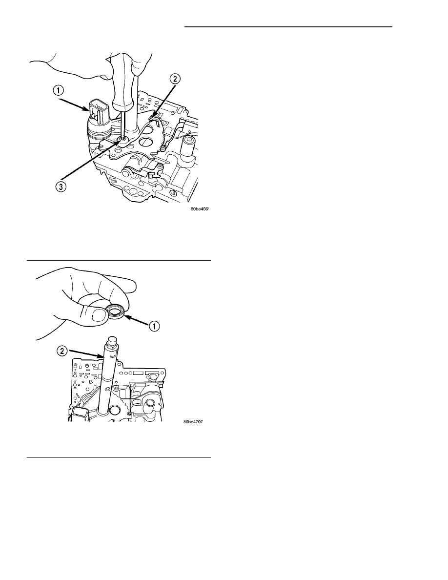
Fig. 413 Install Transmission Range Sensor
Retaining Screw
1 - TRANSMISSION RANGE SENSOR
2 - MANUAL VALVE CONTROL PIN
3 - RETAINING SCREW
Fig. 414 Manual Shaft Seal
1 - SEAL
2 - MANUAL SHAFT
21 - 314
40TE AUTOMATIC TRANSAXLE
PT
VALVE BODY (Continued)