Chrysler Pacifica. Manual - part 843


  Index      Chrysler     Chrysler Pacifica - service repair manual 2005 year


Search            


Content   ..  841  842  843  844   ..


Chrysler Pacifica. Manual - part 843


(4) Adjust the front surface of the sunroof glass

panel 0.00 mm to 1.75 mm (0.00 in. to 0.07 in.) below
the top surface of the roof.

(5) Tighten the front glass panel attaching screws

to 3.5 N·m (31 in. lbs.) torque (Fig. 1).

(6) Loosen the rear screws on each side enough to

make the rear adjustment (Fig. 1).

(7) Adjust the rear surface of the sunroof glass

panel 0.00 mm to 1.75 mm (0.03 in. to 0.07 in.) above
the top surface of the roof.

(8) Tighten the rear glass panel attaching screws

to 3.5 N·m (31 in. lbs.) torque (Fig. 1).

(9) Check for proper fit. If not OK, repeat glass

panel adjustment.

MODULE ASSEMBLY

REMOVAL

(1) Move glass panel to the fully closed position.
(2) Disconnect battery negative cable.
(3) Remove headliner (Refer to 23 - BODY/INTE-

RIOR/HEADLINER - REMOVAL).

(4) Disconnect the four drain tubes from sunroof

housing. (Refer to 23 - BODY/SUNROOF/DRAIN
TUBE - REMOVAL).

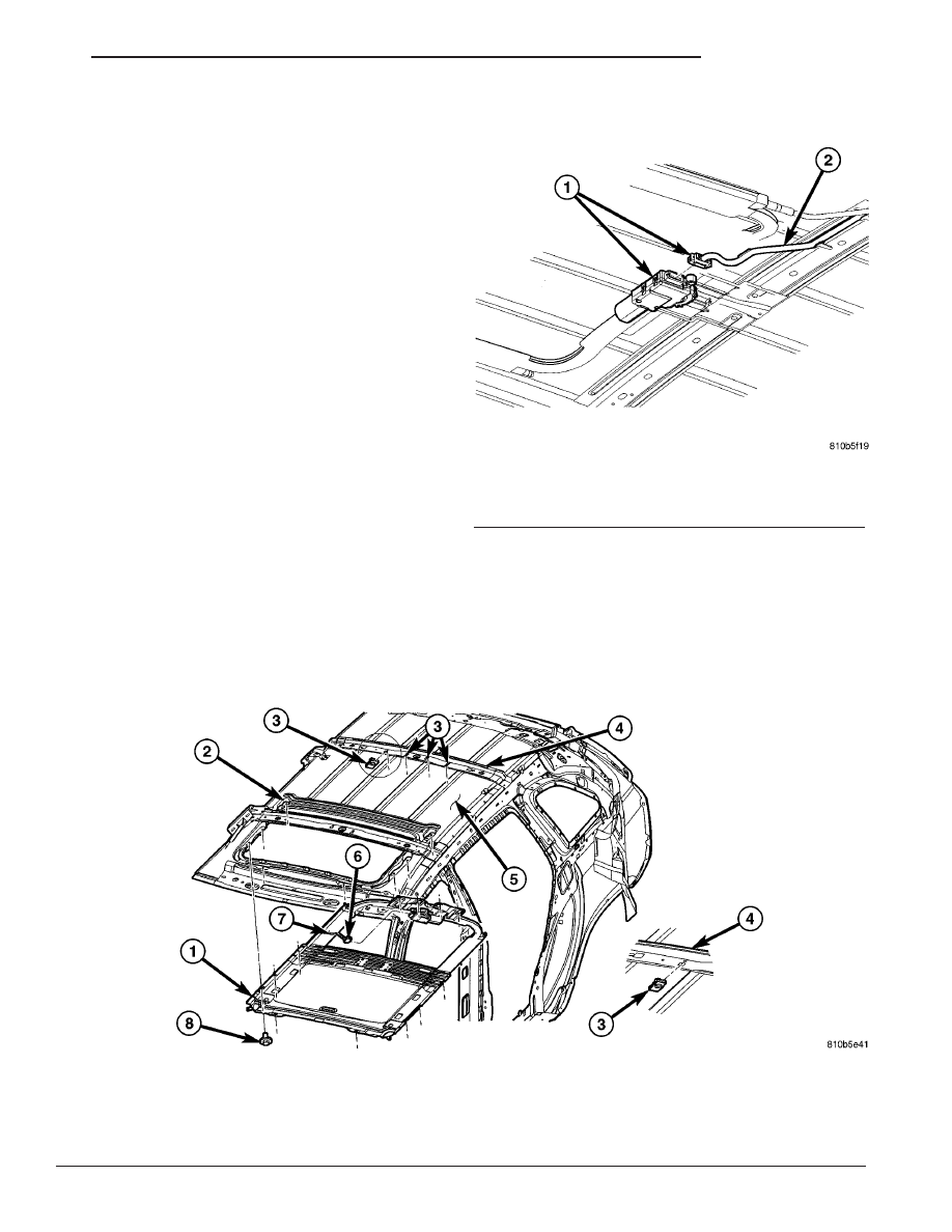
(5) Disconnect sunroof wire connector (Fig. 11)
(6) Loosen fasteners attaching sunroof assembly

(Fig. 12).

(7) With the aid of a helper, support the sunroof

and remove the fasteners attaching sunroof assembly
to roof panel.

(8) Remove sunroof from vehicle.

Fig. 11 SUNROOF WIRE CONNECTOR

1 - WIRE CONNECTOR TO SUNROOF MODULE
2 - BODY WIRE HARNESS

Fig. 12 SUNROOF MODULE

1 - SUNROOF ASSEMBLY
2 - SUNROOF MODULE IN POSITION
3 - SUNROOF MODULE TO ROOF U-NUTS
4 - ROOF BOW #2
5 - ROOF PANEL

6 - SUNROOF WIRE CONNECTOR
7 - BODY WIRE HARNESS
8 - SUNROOF MODULE TO ROOF ATTACHING SCREW(S) AND
WASHER(S)

CS

SUNROOF

23 - 167

GLASS PANEL (Continued)

INSTALLATION

(1) Ensure that u-nuts are in position in the roof

bow #2 (Fig. 13).

(2) Raise sunroof module assembly and guide it

carefully into position (Fig. 12).

(3) While supporting the sunroof assembly start

the attaching screws. Tighten the attaching screws in
sequence to 6 N·m (53 in. lbs.) torque (Fig. 14).

(4) Connect sunroof wire connector (Fig. 11).
(5) Connect the drain tubes to the sunroof (Refer

to 23 - BODY/SUNROOF/DRAIN TUBE - INSTAL-
LATION).

(6) Connect battery negative cable.
(7) Test sunroof operation, adjust as necessary

(Refer to 23 - BODY/SUNROOF/GLASS PANEL -
ADJUSTMENTS).

(8) Install headliner (Refer to 23 - BODY/INTERI-

OR/HEADLINER - INSTALLATION).

SUNSHADE

REMOVAL

(1) Place the sunroof glass panel in the vent posi-

tion.

(2) Remove glass panel (Refer to 23 - BODY/SUN-

ROOF/GLASS PANEL - REMOVAL).

(3) Remove water channel (Fig. 1).
(4) Cycle sunroof motor to the open position.
(5) Move sunshade towards the closed position

stopping three to four inches from the closed position.

(6) Depress the spring feet clips on one side of the

sun shade.

(7) Remove sunshade.

INSTALLATION

(1) Place one side of the sunshade spring feet clips

into the top track U-frame.

(2) Depress the both releasing clips on the other

side to allow them to go into the top track U-frame.

(3) Move sunshade to the open position.
(4) Install water channel (Fig. 1).
(5) Verify that the sunshade move back and forth

properly.

(6) Cycle sunroof towards the closed position.
(7) Install glass panel (Refer to 23 - BODY/SUN-

ROOF/GLASS PANEL - INSTALLATION).

WATER CHANNEL

REMOVAL

(1) Remove glass panel (Refer to 23 - BODY/SUN-

ROOF/GLASS PANEL - REMOVAL).

(2) Remove the retaining screws (Fig. 1).
(3) Carefully

slide

water

channel

forward

to

release tabs from U-frame and remove from vehicle.

INSTALLATION

(1) Carefully place water channel onto U-frame

and slide it rearward to lock tabs (Fig. 1).

(2) Install the water channel attaching screws

(Fig. 1).

(3) Position glass panel on to mechanism lift arms.
(4) Start the glass attaching screws, and hand

tighten.

(5) Adjust sunroof glass (Refer to 23 - BODY/SUN-

ROOF/GLASS PANEL - ADJUSTMENTS).

(6) Verify sunroof operation and alignment.

Fig. 13 ATTACHING U-NUTS

1 - U-NUTS
2 - ROOF BOW #2

Fig. 14 TIGHTENING SEQUENCE

1 - POWER SUNROOF MODULE
2 - LOCATION(S)

23 - 168

SUNROOF

CS

MODULE ASSEMBLY (Continued)

WIND DEFLECTOR

REMOVAL

(1) Fully open sunroof glass panel.
(2) Disconnect negative battery cable.
(3) Remove sunroof assembly (Refer to 23 - BODY/

SUNROOF/MODULE ASSEMBLY - REMOVAL).

(4) Depress the front deflector retaining tabs. (Fig.

15)

(5) Remove wind deflector.

INSTALLATION

(1) Place wind deflector arms in upward position

engage the wind deflector blade into the U-frame
(Fig. 15).

(2)

Engage the retaining clips (Fig. 1).

(3) Verify wind deflector operation.
(4) Install the sun roof assembly (Refer to 23 -

BODY/SUNROOF/MODULE ASSEMBLY - INSTAL-
LATION).

Fig. 15 WIND DEFLECTOR

1 - Sun Roof
2 - Retaining Clip
3 - Sun Roof Assembly Trim

CS

SUNROOF

23 - 169

WEATHERSTRIP/SEALS

TABLE OF CONTENTS

page

page

WEATHERSTRIP/SEALS

DESCRIPTION

. . . . . . . . . . . . . . . . . . . . . . . . 171

DOOR OPENING SEAL - INNER

REMOVAL

. . . . . . . . . . . . . . . . . . . . . . . . . . . . 171

INSTALLATION

. . . . . . . . . . . . . . . . . . . . . . . . 171

FRONT DOOR HEADER WEATHERSTRIP

REMOVAL

. . . . . . . . . . . . . . . . . . . . . . . . . . . . 172

INSTALLATION

. . . . . . . . . . . . . . . . . . . . . . . . 172

FRONT DOOR OPENING WEATHERSTRIP

REMOVAL

. . . . . . . . . . . . . . . . . . . . . . . . . . . . 172

INSTALLATION

. . . . . . . . . . . . . . . . . . . . . . . . 172

FRONT DOOR OUTER BELT WEATHERSTRIP

REMOVAL

. . . . . . . . . . . . . . . . . . . . . . . . . . . . 173

INSTALLATION

. . . . . . . . . . . . . . . . . . . . . . . . 173

FRONT DOOR MOUNTED WEATHERSTRIP

REMOVAL

. . . . . . . . . . . . . . . . . . . . . . . . . . . . 174

INSTALLATION

. . . . . . . . . . . . . . . . . . . . . . . . 174

FRONT INNER BELT MOLDING

WEATHERSTRIP
REMOVAL

. . . . . . . . . . . . . . . . . . . . . . . . . . . . 175

INSTALLATION

. . . . . . . . . . . . . . . . . . . . . . . . 175

LIFTGATE OPENING WEATHERSTRIP

REMOVAL

. . . . . . . . . . . . . . . . . . . . . . . . . . . . 176

INSTALLATION

. . . . . . . . . . . . . . . . . . . . . . . . 176

LIFTGATE UPPER SECONDARY

WEATHERSTRIP
REMOVAL

. . . . . . . . . . . . . . . . . . . . . . . . . . . . 176

INSTALLATION

. . . . . . . . . . . . . . . . . . . . . . . . 176

REAR DOOR HEADER WEATHERSTRIP

REMOVAL

. . . . . . . . . . . . . . . . . . . . . . . . . . . . 177

INSTALLATION

. . . . . . . . . . . . . . . . . . . . . . . . 177

REAR DOOR INNER BELT MOLDING

WEATHERSTRIP
REMOVAL

. . . . . . . . . . . . . . . . . . . . . . . . . . . . 177

INSTALLATION

. . . . . . . . . . . . . . . . . . . . . . . . 178

REAR DOOR MOUNTED WEATHERSTRIP

REMOVAL

. . . . . . . . . . . . . . . . . . . . . . . . . . . . 178

INSTALLATION

. . . . . . . . . . . . . . . . . . . . . . . . 178

REAR DOOR OUTER BELT MOLDING

REMOVAL

. . . . . . . . . . . . . . . . . . . . . . . . . . . . 179

INSTALLATION

. . . . . . . . . . . . . . . . . . . . . . . . 179

REAR DOOR OPENING WEATHERSTRIP

REMOVAL

. . . . . . . . . . . . . . . . . . . . . . . . . . . . 180

INSTALLATION

. . . . . . . . . . . . . . . . . . . . . . . . 180

23 - 170

WEATHERSTRIP/SEALS

CS


Content   ..  841  842  843  844   ..