Chrysler Pacifica. Manual - part 835


  Index      Chrysler     Chrysler Pacifica - service repair manual 2005 year


Search            


Content   ..  833  834  835  836   ..


Chrysler Pacifica. Manual - part 835


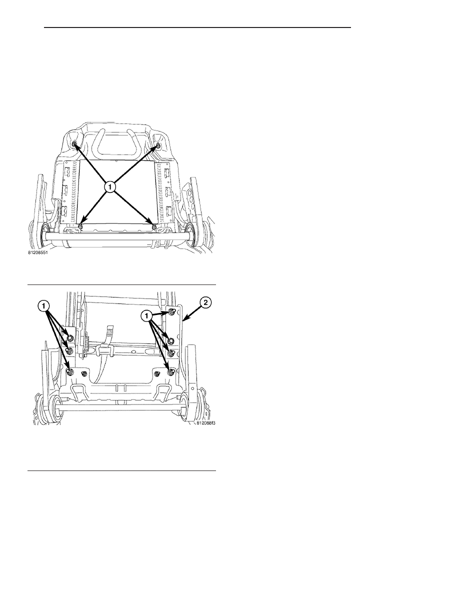
(21) Remove four seat cushion pan nuts (Fig. 46).
(22) Remove seat cushion pan.
(23) Remove two bolts and five nuts attaching

lower recliner bracket to riser and leg assembly (Fig.
47).

(24) Remove

seat

back

frame/recliners/CRAS

bracket and torque rod.

INSTALLATION

(1) Place seat back frame/recliners/CRAS bracket

and torque rod in position on riser and leg assembly.

(2) Install two bolts and five nuts attaching lower

recliner bracket to riser and leg assembly (Fig. 47).
Tighten nuts to 48 N·m (35 ft. lbs.) torque, and
tighten bolts to 29 N·m (35 ft. lbs.) torque.

(3) Place seat cushion pan into position.
(4) Install four seat cushion pan nuts (Fig. 46).

(5) Place seat cushion foam and cover in position

on seat pan (Fig. 45).

(6) Connect the J-strap and install push pin fas-

teners at the rear of seat cushion pan (Fig. 43) and
(Fig. 44).

(7) Route to under side of cushion pad and connect

heat seat wire harness and three attachments.

NOTE: Use care not to damage wire harness during
install procedure.

(8) Install upper recliner bolts to seat back frame,

and tighten bolts to 48 N·m (35 ft. lbs.) torque (Fig.
41) and (Fig. 42).

(9) Place seat foam/cover in position and work the

foam and cover under recliner torque rod (Fig. 39)
and (Fig. 40).

(10) Feed seat back harness through hole in

shield. Connect wiring harness (for heated seats) at
inner shield and feed back harness through hole in
shield (Fig. 38).

(11) Engage inner J-straps (Fig. 37).
(12) Install trim ring (Fig. 36).
(13) Install screws attaching trim ring to seat back

frame (Fig. 35) and (Fig. 36).

(14) Engage outer J-straps at seat back (Fig. 34).
(15) Install three screws attaching outboard side

shield.

(16) Install two screws attaching inboard side

shield.

(17) Press outboard side handle on retainer tab till

it engages.

(18) Install two screws attaching outer side shield

buckle side.

(19) Install seat inner panel. (Refer to 23 - BODY/

SEATS/SECOND ROW SEAT INNER PANEL -
INSTALLATION)

(20) Install armrest. (Refer to 23 - BODY/SEATS/

SEAT ARMREST - INSTALLATION).

(21) Connect heat element wire harness.
(22) Install second row seat. (Refer to 23 - BODY/

SEATS/SECOND ROW SEAT - INSTALLATION).

(23) Install headrest and sleeves (Refer to 23 -

BODY/SEATS/HEADREST - INSTALLATION).

(24) Connect battery negative cable.

SECOND ROW SEAT CUSHION
FOAM/COVER

REMOVAL

(1) Disconnect and isolate the battery negative

cable.

(2) Remove headrest. (Refer to 23 - BODY/SEATS/

HEADREST - REMOVAL).

Fig. 46 SEAT CUSHION PAN

1 - ATTACHING NUTS

Fig. 47 SECOND ROW BACK FRAME/RECLINER/

CRAS BRACKET, AND TORQUE ROD

1 - ATTACHING NUTS AND BOLTS
2 - LOWER RECLINER ASSEMBLY

CS

SEATS

23 - 135

SECOND ROW SEAT BACK FRAME/RECLINER/TORQUE ROD/CRAS ASSEMBLY (Continued)

(3) Remove second row seat. (Refer to 23 - BODY/

SEATS/FIRST ROW SEAT - REMOVAL).

(4) Disconnect heat element wire harness.
(5) Remove two screws attaching outer side shield

buckle side.

(6) Remove screw attaching floor dump release

handle and remove handle.

(7) Remove front recliner handle (snaps on).
(8) Remove three screws attaching side shield at

recliner handle side.

(9) Remove three screws attaching inner side

shield hinge area.

(10) Remove hinge to floor plastic cover.
(11) Remove four screws attaching lower plastic

cover, under side of seat.

(12) Disengage J-straps and push pins at cushion

cover (Fig. 48).

(13) Remove cushion and cover from seat pan.
(14) Remove cover from cushion.

INSTALLATION

(1) Place cover on cushion (Fig. 48).
(2) Install cushion and cover to seat pan.
(3) Engage J-straps and push pins to seat pan.
(4) Install four screws attaching lower plastic

cover, to under side of seat.

(5) Install hinge to floor plastic cover.
(6) Install three screws attaching inner side shield

hinge area.

(7) Install three screws attaching side shield at

recliner handle side.

(8) Push on front recliner handle to lock into posi-

tion.

(9) Install screw attaching floor dump release han-

dle.

(10) Install two screws attaching outer side shield

buckle side.

(11) Connect heat element wire harness.
(12) Install first row seat. (Refer to 23 - BODY/

SEATS/SECOND ROW SEAT - INSTALLATION).

(13) Install headrest. (Refer to 23 - BODY/SEATS/

HEADREST - INSTALLATION).

(14) Connect battery negative cable.

SECOND ROW SEAT RISER

REMOVAL

(1) Disconnect and isolate the battery negative

cable.

(2) Remove headrest. (Refer to 23 - BODY/SEATS/

HEADREST - REMOVAL).

(3) Remove second row seat. (Refer to 23 - BODY/

SEATS/SECOND ROW SEAT - REMOVAL).

(4) Disconnect heat element wire harness.
(5) Turn seat over (Fig. 49).
(6) Remove four nuts attaching seat base to seat

assembly.

(7) Remove seat base.

INSTALLATION

(1) Place seat base into position on second seat

assembly.

(2) Install four nuts attaching seat base to seat

assembly (Fig. 49).

(3) Place seat into position.
(4) Connect heating element wire harness.

Fig. 48 SEAT BACK CUSHION

1 - SECOND ROW SEAT CUSHION COVER
2 - SECOND ROW SEAT CUSHION
3 - SEAT HEATING ELEMENT WIRE HARNESS
4 - SEAT HEATING ELEMENT

Fig. 49 SEAT RAISER

1 - SEAT BASE
2 - SECOND ROW SEAT ASSEMBLY

23 - 136

SEATS

CS

SECOND ROW SEAT CUSHION FOAM/COVER (Continued)

(5) Install second row seat. (Refer to 23 - BODY/

SEATS/SECOND ROW SEAT - INSTALLATION).

(6) Install headrest. (Refer to 23 - BODY/SEATS/

HEADREST - INSTALLATION).

(7) Disconnect and isolate the battery negative

cable.

SECOND ROW SEAT SIDE
SHIELD

REMOVAL

(1) Fold seat flat and tilt seat forward to access

screw.

(2) Remove screw attaching second row seat side

shield (Fig. 50).

(3) Remove side shield.

INSTALLATION

(1) Place side shield into position.
(2) Install screw attaching second row seat side

shield (Fig. 50).

THIRD ROW SEAT

REMOVAL

(1) Open liftgate.
(2) Remove rear floor stowage bin. (Refer to 23 -

BODY/INTERIOR/REAR FLOOR STOWAGE BIN -
REMOVAL).

(3) Remove third row seat rear two attaching bolts

(Fig. 51).

(4) Remove third row seat front covers. (Fig. 52).
(5) Remove the third row seat front two attaching

bolts.

(6) Remove seat from vehicle.

Fig. 50 SEAT CUSHION SIDE SHIELD

1 - SECOND ROW SEAT SIDE SHIELD
2 - ATTACHING SCREW

Fig. 51 THIRD ROW SEAT - REAR SCREWS

1 - THIRD ROW SEAT BACK
2 - REAR ATTACHING BOLTS
3 - REAR FLOOR STOWAGE BIN

CS

SEATS

23 - 137

SECOND ROW SEAT RISER (Continued)

INSTALLATION

(1) Place seat into position in vehicle.
(2) Install third row seat front two attaching bolts

and tighten to 88 N·m (65 ft. lbs.) torque (Fig. 52).

(3) Install third row seat front covers.
(4) Install third row seat two rear attaching bolts

and tighten to 88 N·m (65 ft. lbs.) torque (Fig. 51).

(5) Install rear floor stowage bin. (Refer to 23 -

BODY/INTERIOR/REAR FLOOR STOWAGE BIN -
INSTALLATION).

THIRD ROW SEAT BACK
CUSHION FOAM/ COVER

REMOVAL

(1) Open liftgate.
(2) Remove rear floor stowage bin. (Refer to 23 -

BODY/INTERIOR/REAR FLOOR STOWAGE BIN -
REMOVAL).

(3) Remove third row seat. (Refer to 23 - BODY/

SEATS/THIRD ROW SEAT - REMOVAL).

(4) Using finger, disengage fold flat cable from

handle (Fig. 53).

Fig. 52 THIRD ROW SEATS

1 - ATTACHING WASHERS AND BOLTS
2 - THIRD ROW BUCKET SEATS
3 - FLOOR PAN

4 - CARPETING
5 - THIRD ROW SEAT FRONT COVER

Fig. 53 FOLD FLAT CABLE

1 - RELEASE CABLE

23 - 138

SEATS

CS

THIRD ROW SEAT (Continued)


Content   ..  833  834  835  836   ..