Chrysler Pacifica. Manual - part 815


  Index      Chrysler     Chrysler Pacifica - service repair manual 2005 year


Search            


Content   ..  813  814  815  816   ..


Chrysler Pacifica. Manual - part 815


(3) Remove protective cover from tape on back of

molding.

(4) Apply molding to body from front to rear,

inserting locator pins into holes in body panel (Fig. 8)
or (Fig. 9).

(a) Align front self locating pin to vehicle first.
(b) Then rear locating pins to the 4-way slots

(5) Using a roller tool, roll molding onto body

panel with enough force to assure adhesion. Do not
apply excessive force, or damage to body panels may
result.

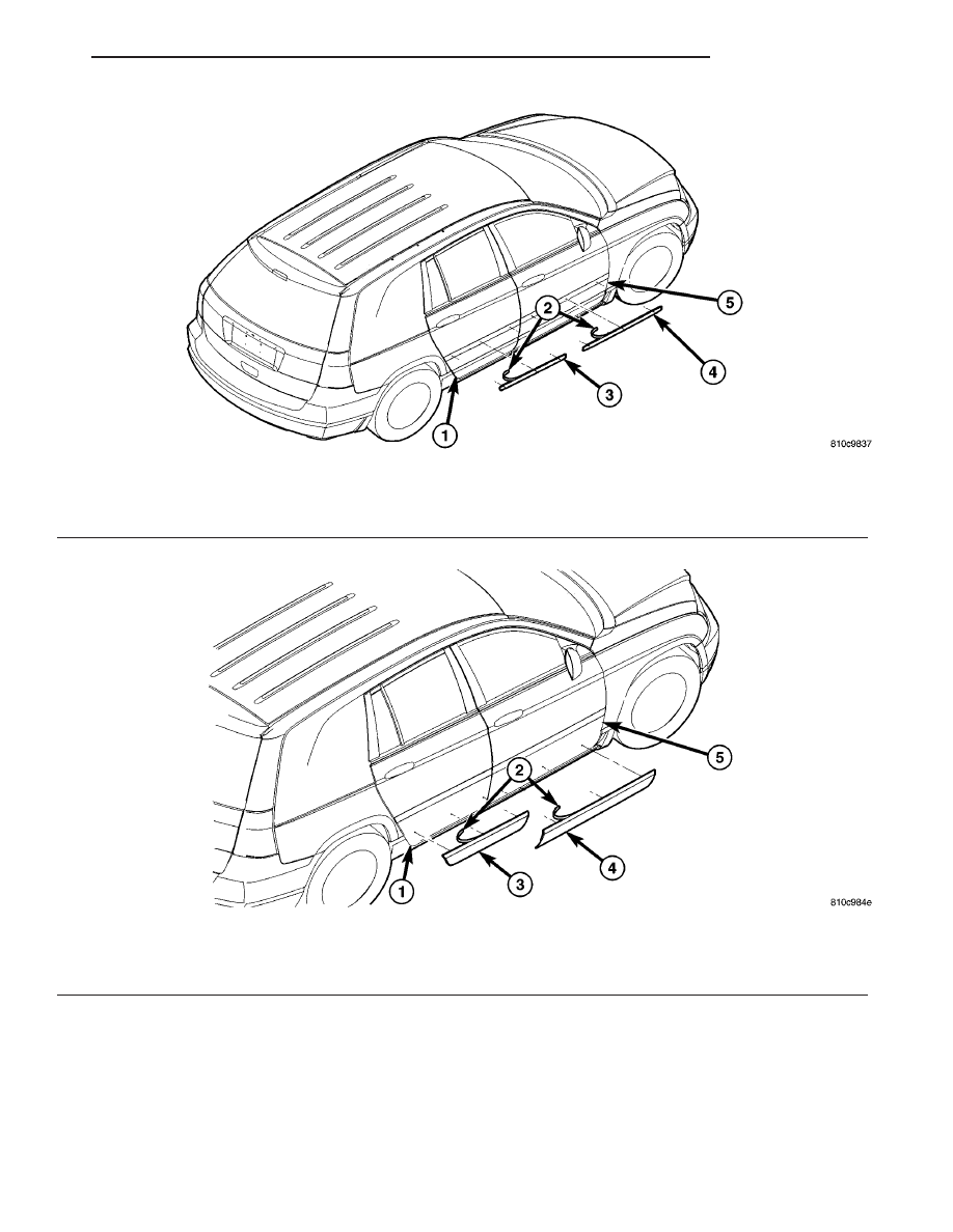
Fig. 8 FRONT AND REAR DOOR OUTSIDE MOLDING

1 - REAR DOOR PANEL
2 - ADHESIVE TAPE BACKING
3 - REAR DOOR OUTSIDE MOLDING

4 - FRONT DOOR OUTSIDE MOLDING
5 - FRONT DOOR PANEL

Fig. 9 FRONT AND REAR DOOR OUTSIDE APPLIQUE

1 - REAR DOOR PANEL
2 - ADHESIVE TAPE BACKING
3 - REAR DOOR OUTSIDE APPLIQUE

4 - FRONT DOOR OUTSIDE APPLIQUE
5 - FRONT DOOR PANEL

CS

EXTERIOR

23 - 55

BODY SIDE CLADDING (Continued)

COWL PLENUM GRILLE

REMOVAL

(1) Remove wiper arms. (Refer to 8 - ELECTRI-

CAL/WIPERS/WASHERS/WIPER

ARMS

-

REMOVAL).

(2) Release hood latch and open hood, as neces-

sary.

(3) Remove the two (2) push pin fasteners securing

cowl plenum grille to top cowl plenum panel (Fig.
10).

(4) Using a trim stick C-4755 or equivalent, disen-

gage the locking tabs and remove cowl plenum grill
from the body.

CAUTION: To prevent hood scratching of cowl grille
before removal, cover outboard exterior ends of
cowl plenum grille with masking tape or equivalent
method.

NOTE: Do not over bend cowl plenum grille during
removal. Bend cowl plenum grille just enough to
clear top of wiper pivot shaft and bottom rear cor-
ner of hood.

(5) Remove cowl plenum grille from vehicle.

INSTALLATION

(1) Open hood, as necessary.
(2) Place cowl plenum grille into position.
(3) Press down on cowl plenum grille to lock the

locking tabs.

(4) Install the two (2) push pin fasteners securing

cowl plenum grille to top cowl plenum panel (Fig.
10).

(5) Remove wiper arms. (Refer to 8 - ELECTRI-

CAL/WIPERS/WASHERS/WIPER ARMS - INSTAL-
LATION).

EXHAUSTER

REMOVAL

(1) Using a trim stick C-4755 or equivalent, pry

exhauster grille from the lower center edge of the
grille (Fig. 11).

(2) Remove grille from opening.

INSTALLATION

(1) Place exhauster grille into opening.
(2) Work the exhauster grille lip into position in

opening (Fig. 11).

Fig. 10 COWL PLENUM GRILLE

1 - PUSH PIN FASTENER
2 - WIPER ARM NUT CAP
3 - WIPER ARM ATTACHING NUT
4 - WIPER ARM AND BLADE
5 - LOWER HALF HOOD HINGE
6 - COWL PLENUM CLIP(S)
7 - COWL PLENUM FRONT PANEL
8 - TOP COWL PLENUM PANEL
9 - COWL PLENUM GRILLE

Fig. 11 EXHAUSTER GRILLE

1 - AREA BEHIND REAR FASCIA
2 - EXHAUSTER GRILLE
3 - REMOVAL AREA

23 - 56

EXTERIOR

CS

EXTERIOR NAME PLATES -
ADHESIVE

REMOVAL

(1) Mark reference points before removing.
(2) Using a heat gun gently apply heat in a circu-

lar motion to loosen the adhesive bond.

(3) With your fingernail lift up and peel away

name plates/tape from panel, using a heat gun as
you go.

(4) Clean off all traces of adhesive from the pan-

el(s) with a general purpose adhesive remover.

INSTALLATION

(1) Clean panel surface with isopropy alcohol.
(2) Remove paper carrier and align name plates/

tape to reference points or adjacent panel.

(3) Install and press securely, using a plastic

spreader to eliminate all air bubbles.

(4) Remove top protective carrier.
(5) Clean away any reference points.

EXTERIOR NAME PLATES -
TAPE

REMOVAL

(1) Mark reference points before removing.
(2) Using a heat gun gently apply heat in a circu-

lar motion to loosen the adhesive bond.

(3) Using a nonmetallic prying device, such as a

plastic or wood trim stick gently pry up at corners
and remove.

(4) Clean off all traces of adhesive or double sided

tape from the panel with a general purpose adhesive
remover.

INSTALLATION

(1) Clean panel surface with isopropy alcohol.
(2) Align name plates to reference points.
(3) Install and press securely to full adhesive con-

tact

(4) Clean away any reference points.

FRONT FENDER

REMOVAL

(1) Remove headlamp housing. (Refer to 8 - ELEC-

TRICAL/LAMPS/LIGHTING

-

EXTERIOR/HEAD-

LAMP UNIT - REMOVAL).

(2) Remove inner splash shield. (Refer to 23 -

BODY/EXTERIOR/LF

WHEELHOUSE

SPLASH

SHIELD - REMOVAL).

(3) Remove fender to fascia fasteners.
(4) Remove outboard cowl grille/fender bracket

screw (Fig. 12).

(5) Remove fender screws to lower sill panel (Fig.

13).

Fig. 12 FENDER BRACKET TO COWL ATTACHING

SCREWS

1 - FRONT FENDER
2 - ATTACHING SCREW

Fig. 13 FENDER TO SILL ATTACHING SCREWS

1 - FRONT FENDER
2 - ATTACHING SCREWS

CS

EXTERIOR

23 - 57

(6) Remove fender screw to A-pillar (Fig. 14).
(7) Pull fascia away from fender.
(8) Remove bolts attaching fender to side shield

(Fig. 15).

(9) From inside engine compartment, remove bolts

attaching fender to upper rail (Fig. 16).

(10) Remove fender from vehicle.

INSTALLATION

(1) Place fender in position on vehicle.
(2) From inside engine compartment, start the

fender attaching screws to upper rail (Fig. 16).

(3) Pull fascia away from fender.
(4) Start screws attaching fender to side shield

(Fig. 15)

(5) Start fender screw to A-pillar (Fig. 14).
(6) Start fender screws to lower sill panel (Fig. 13).
(7) Start outboard cowl grille/fender bracket screw

(Fig. 12).

(8) With all screws started check fender for proper

alignment. (Refer to 23 - BODY/BODY STRUCTURE/
GAP AND FLUSH - SPECIFICATIONS).

(9) Tighten all fender screws to 9 N·m (80 in. lbs.)

torque.

Fig. 14 FENDER TO A-PILLAR ATTACHING SCREWS

1 - FRONT FENDER
2 - ATTACHING SCREW

Fig. 15 FENDER TO BODY ATTACHING SCREWS

1 - FRONT FENDER
2 - ATTACHING SCREWS

Fig. 16 FRONT FENDER

1 - FRONT FENDER
2 - ATTACHING SCREWS AND TIGHTENING SEQUENCE

23 - 58

EXTERIOR

CS

FRONT FENDER (Continued)


Content   ..  813  814  815  816   ..