Chrysler Pacifica. Manual - part 797


  Index      Chrysler     Chrysler Pacifica - service repair manual 2005 year


Search            


Content   ..  795  796  797  798   ..


Chrysler Pacifica. Manual - part 797


NOTE: When using Radial Force equipment, it is
critically important to set proper tire inflation pres-
sure and ensure centering of the wheel on the
equipment spindle.

RADIAL FORCE VARIATION REFERENCE

VALUES

DESCRIPTION

SPECIFICATION

Total Radial Force
Variation (RFV)

Less Than 22 Lbs. ± 2

Lbs.

Radial First Harmonic
(R1H)

Less Than 16 Lbs. ± 2

Lbs.

Radial Second Harmonic
(R2H)

Less Than 12 Lbs. ± 2

Lbs.

STANDARD PROCEDURE - TIRE AND WHEEL
BALANCE

NOTE: Balance equipment must be calibrated and
maintained per equipment manufacturer’s specifica-
tions.

Wheel balancing can be accomplished with either

on-vehicle or off-vehicle equipment.

NOTE: If using on-vehicle balancing equipment, on
the driving axle, remove the opposite wheel and tire
assembly.

It is recommended that a two-plane dynamic bal-

ancer be used when a wheel and tire assembly
requires balancing. A static balancer should only be
used when a two-plane balancer is not available.

Balance wheel and tire assemblies dynamically and

statically to less than 0.25 (

1

4

) ounce.

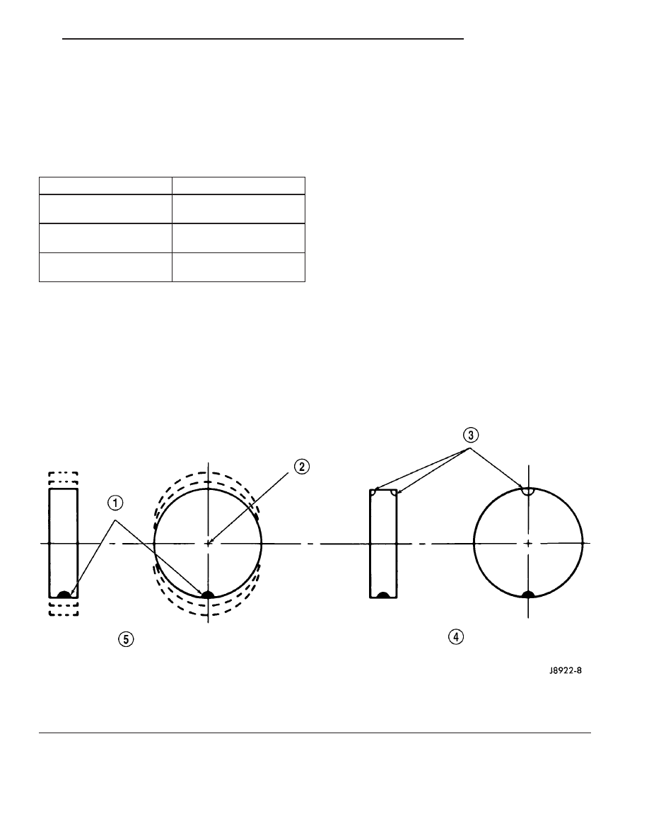
For static balancing, find location of heavy spot

causing imbalance. Counter balance wheel directly
opposite the heavy spot. Determine weight required
to counterbalance the area of imbalance. Place half of
this weight on the inner rim flange and the other
half on the outer rim flange (Fig. 8).

For dynamic balancing, the balance equipment is

designed to indicate the location and amount of
weight to be applied to both the inner and outer rim
flanges (Fig. 9).

Fig. 8 Static Unbalance & Balance

1 - HEAVY SPOT

4 - CORRECTIVE WEIGHT LOCATION

2 - CENTER LINE OF SPINDLE

5 - TIRE OR WHEEL TRAMP, OR WHEEL HOP

3 - ADD BALANCE WEIGHTS HERE

CS

TIRES/WHEELS

22 - 5

TIRES/WHEELS (Continued)

The aluminum wheels on this vehicle use a unique

wheel weight (Fig. 10). This wheel weight is designed
to fit the contoured surface of the wheel (Fig. 10).
When balancing an aluminum wheel, this wheel
weight must be used. Do not use any other type of
wheel weight. It will not properly fit the contour of
the wheel.

Always verify the Balance. When using off-vehicle

equipment, rotate assembly 180 degrees on balance
equipment to verify balance. Variation should not be
more than 0.125 (

1

8

) ounce. If variation is more than

0.125 ounce, balancing equipment could be malfunc-
tioning.

If difficult to balance, break down the wheel and

tire assembly and check for loose debris inside tire.
Prior to disassembly, mark (index) the tire at the
valve stem. Use this mark in order to remount the
tire in its original orientation with respect to the
wheel.

REMOVAL - TIRE AND WHEEL ASSEMBLY
(ALUMINUM WHEEL)

(1) Raise the vehicle so the tire and wheel assem-

bly clears ground level.

(2) Remove the 5 wheel mounting nuts from the

studs.

(3) Remove the tire and wheel from the hub.

INSTALLATION - TIRE AND WHEEL ASSEMBLY
(ALUMINUM WHEEL)

NOTE: Never use oil or grease on studs or wheel
mounting nuts.

(1) Position the tire and wheel assembly on the

wheel mounting studs using the hub pilot as a guide.
Place and hold the wheel flush up against the mount-
ing surface.

Fig. 9 Dynamic Unbalance & Balance

1 - CENTER LINE OF SPINDLE

3 - CORRECTIVE WEIGHT LOCATION

2 - ADD BALANCE WEIGHTS HERE

4 - HEAVY SPOT WHEEL SHIMMY AND VIBRATION

Fig. 10 Aluminum Wheel Weight

1 - TIRE
2 - WHEEL
3 - WHEEL WEIGHT

22 - 6

TIRES/WHEELS

CS

TIRES/WHEELS (Continued)

(2) Loosely install all 5 wheel mounting nuts.

Lightly snug the wheel nuts, then progressively
tighten them in the proper sequence (Fig. 11).
Tighten wheel mounting nuts to 135 N·m (100 ft.
lbs.).

(3) Lower the vehicle.

TIRE PRESSURE MONITORING

DESCRIPTION

The Tire Pressure Monitoring (TPM) system moni-

tors air pressure in the four road tires. Pressure in
the spare tire is not monitored.

The system alerts the driver when tire pressure

falls outside predetermined thresholds. (Refer to 22 -
TIRES/WHEELS/TIRE PRESSURE MONITORING -
OPERATION)

There is a sensor (transmitter) located in each of

the vehicle’s four road wheels that operates on a 315
MHz radio frequency (Fig. 12).

The TPM system is controlled by the Sentry Key

Remote Entry Module (SKREEM). When Diagnosing
the TPM, use a scan tool accessing the SKREEM.

An indicator lamp located in the instrument clus-

ter and the Electronic Vehicle Information Center
(EVIC) are used to communicate system information.

For further information, refer to the Owners Man-

ual or the appropriate diagnostic information.

OPERATION

The Tire Pressure Monitoring (TPM) system uses

radio and sensor technology to monitor tire air pres-
sure levels. Sensors, mounted to each road wheel as
part of the valve stem, transmit an RF signal indi-
cating their individual pressure to a receiver located
in the Sentry Key Remote Entry Module (SKREEM).
These transmissions occur approximately once every
minute at speeds over 15 mph (24 km/h). The Tire

Pressure Monitoring system remains active even if
no tire pressure related message is displayed.

The sensors lay dormant (Park Mode), then wake

and start transmitting (Drive Mode) when the vehicle
first reaches speeds over 15 mph (24 km/h). Once the
wheels stop rotating for a period of approximately 20
minutes, the sensors shut down until again awaken.
Although not transmitting as when in Drive Mode,
while in Park Mode, the sensors still transmit
approximately once every 13 hours to let the receiver
know air pressure status at that time.

If the system detects that the tire pressure in any

road tire is going low, beyond the Low Pressure
(lamp) ON threshold (see following table), the TPM
system will display a message in the instrument
cluster and continuously illuminate an indicator
lamp. This message will be displayed for the rest of
the ignition cycle, or until the Low Tire pressure con-
dition has been corrected. Once pressure in the sus-
pect tire raises above the Low Pressure (lamp) OFF
Threshold, the lamp will go out and the system
returns to normal within approximately two minutes
time. If the C/T, MENU, STEP or RESET button is
pressed, the message is replaced by the new message
requested; however, if the Low Tire condition has not
been corrected, the Low Tire pressure message will
again be displayed.

If a system fault is detected, the indicator lamp

will flash on/off for 10 seconds, once every 10 min-
utes.

For further information, refer to the Owners Man-

ual or the Appropriate Diagnostic Information.

Fig. 11 Tightening Sequence

Fig. 12 Tire Pressure Sensor

1 - ANTENNA STRAP
2 - VALVE STEM

CS

TIRES/WHEELS

22 - 7

TIRES/WHEELS (Continued)

TPM THRESHOLD PRESSURES

High Pressure ON Threshold

48 PSI (331 kPa)

High Pressure OFF Threshold

43 PSI (296 kPa)

Placard Pressure (Cold)

33 PSI (228 kPa)

Low Pressure OFF Threshold

30 PSI (207 kPa)

Low Pressure ON Threshold

26 PSI (179 kPa)

SENSOR - TPM

DESCRIPTION

On vehicles equipped with Tire Pressure Monitor-

ing (TPM), one tire pressure sensor is mounted to
each wheel in place of the traditional tire valve stem
(Fig. 13). Each sensor has an internal battery that
lasts up to 10 years. The battery is not serviceable.
At the time of battery failure, the sensor must be
replaced.

The TPM system operates on a 315 MHz radio fre-

quency (Fig. 13).

The TPM sensors are designed for original style

factory wheels. Do not attempt to install a tire
pressure sensor in an aftermarket wheel.

The serviceable components of the tire pressure

sensor are (Fig. 14):

• Sensor-To-Wheel Seal and Metal Washer

• Valve Stem Cap

• Valve Stem Core

• Valve Stem Nut
The valve stem caps and cores used are specifically

designed for the tire pressure monitoring sensors.

Although similar to standard valve stem caps and
cores, they are different. The valve stem cap has a
special seal inside to keep moisture and corrosion
out. The valve stem core has a special nickel coating
to protect from corrosion.

OPERATION

The battery operated tire pressure sensors lay dor-

mant (Park Mode), then wake and start transmitting
(Drive Mode) when the vehicle first reaches speeds
over 15 mph (24 km/h). Once the wheels stop rotat-
ing for a period of approximately 20 minutes, the
sensors shut down until again awaken. Although not
transmitting as when in Drive Mode, while in Park
Mode, the sensors still transmit approximately once
every 13 hours to let the receiver know air pressure
status at that time.

Using an RF signal, each sensor transmits tire

pressure data approximately once every minute.
Each sensor’s (transmitter) broadcast is uniquely
coded so that the Sentry Key Remote Entry Module
(SKREEM) can monitor the state of each of the sen-
sors on the four rotating road wheels. The SKREEM
automatically learns and stores the sensor’s ID while
driving after a sensor has been replaced. There is
no formal retraining procedure necessary.

For additional information, refer to appropriate

diagnostic information.

Fig. 13 Tire Pressure Sensor

1 - ANTENNA STRAP
2 - VALVE STEM

Fig. 14 Sensor Mounting - Exploded View

1 - METAL WASHER
2 - SEAL
3 - NUT (WITH PRESSED-IN WASHER)
4 - CAP (WITH SEAL)
5 - SECTIONAL CUTAWAY OF WHEEL
6 - TPM SENSOR

22 - 8

TIRES/WHEELS

CS

TIRE PRESSURE MONITORING (Continued)


Content   ..  795  796  797  798   ..