Chrysler Pacifica. Manual - part 738


  Index      Chrysler     Chrysler Pacifica - service repair manual 2005 year


Search            


Content   ..  736  737  738  739   ..


Chrysler Pacifica. Manual - part 738


(2) Carefully place idle air control motor into

throttle body (Fig. 51).

(3) Install mounting screw(s). Tighten mounting

screw to 5.5 N·m (49 in. lbs.) torque.

(4) Connect electrical connector to idle air control

motor.

(5) Connect negative cable to battery.

INTAKE AIR TEMPERATURE
SENSOR

REMOVAL

(1) Disconnect the negative battery cable.
(2) Unlock and disconect the electrical connector

(Fig. 52).

(3) remove sensor from hose.

INSTALLATION

(1) Install sensor into inlet hose.
(2) Connect and lock the electrical connector (Fig.

52).

(3) Connect the negative battery cable.

MANIFOLD TUNE VALVE

REMOVAL

(1) Disconnect the negative battery cable.
(2) Remove the engine cover.

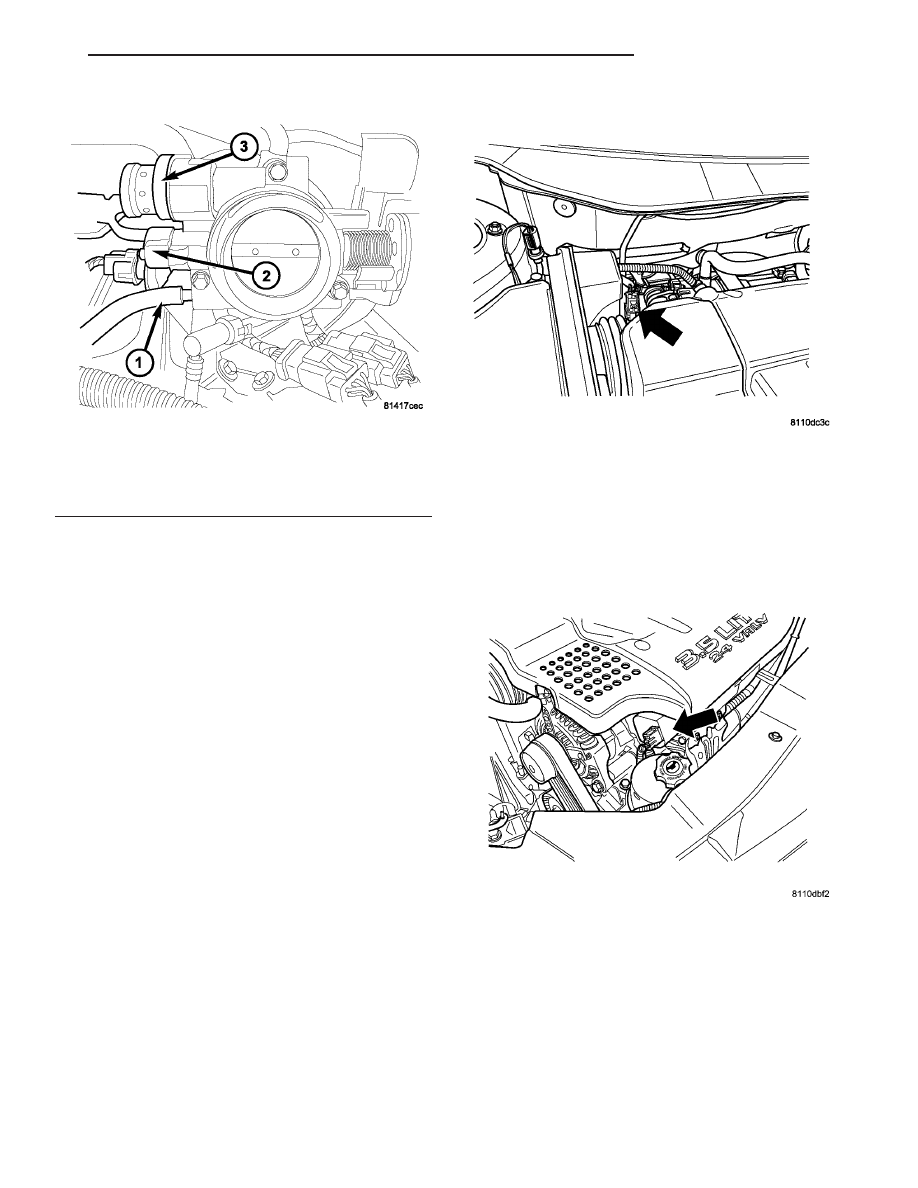
Fig. 51 THROTTLE BODY

1 - Purge Line
2 - Throttle Position Sensor
3 - Idle Air Control Motor

Fig. 52 INTAKE AIR TEMPERATURE SENSOR

MANIFOLD TUNING VALVE

CS

FUEL INJECTION

14 - 43

IDLE AIR CONTROL MOTOR (Continued)

(3) Disconnect the electrical connector (Fig. 53).

(4) Remove the 4 mounting bolts (Fig. 54).

(5) Pull valve straight out of manifold (Fig. 55).

INSTALLATION

(1) Install the manifold tuning valve, make sure

that the alignment pin (Fig. 56) and notch line up.

(2) Install bolts and tighten.
(3) Connect the electrical connector.
(4) Install the engine cover.
(5) Connect the negative battery cable.

Fig. 53 MANIFOLD TUNING VALVE ELECTRICAL

CONNECTOR

Fig. 54 MTV VALVE

Fig. 55 MTV VALVE REMOVED

Fig. 56 MTV LOCATING PIN

14 - 44

FUEL INJECTION

CS

MANIFOLD TUNE VALVE (Continued)

MAP SENSOR

REMOVAL

3.5L

(1) Remove the negative battery cable.
(2) Disconnect the electrical connector from the

MAP sensor (Fig. 57).

(3) Remove bolt from sensor.

(4) Remove sensor (Fig. 58).

3.8L

(1) Disconnect negative battery cable.

(2) Unlock and disconnect electrical connector (Fig.

59).

(3) Remove 2 mounting screws.
(4) Remove sensor.

INSTALLATION

3.5L

(1) The sensor mounts onto intake manifold ple-

num (Fig. 60). Tighten screws to 4.5 N·m (40 in. lbs.)
torque.

Fig. 57 MAP SENSOR LOCATION

Fig. 58 MAP SENSOR O-RING

Fig. 59 MAP SENSOR

1 - MAP Sensor
2 - Vacuum Lines

Fig. 60 MAP SENSOR O-RING

CS

FUEL INJECTION

14 - 45

(2) Attach electrical connector to sensor (Fig. 61).
(3) Install the negative battery cable.

3.8L

When servicing components, always reassemble

components with new O-rings and seals where appli-

cable. If assembly of component is difficult, a light
coat of engine oil may be applied to the
O-RINGS ONLY 
to aid assembly.

(1) Install MAP sensor (Fig. 62).
(2) Install and tighten screws.
(3) Connect and lock electrical connector.
(4) Connect negative battery cable.

O2 SENSOR

REMOVAL

REMOVAL

The engines uses two heated oxygen sensors.

CAUTION: When disconnecting the sensor electrical
connector, do not pull directly on wire going into
sensor.

(1) Disconnect the negative battery cable.
(2) Disconnect the heated oxygen sensor electrical

connector.

(3) Use a socket such as Snap-On YA8875 or a

crow foot wrench to remove oxygen sensor (Fig. 63).

Fig. 61 MAP SENSOR LOCATION

Fig. 62 MAP SENSOR

1 - MAP Sensor
2 - Vacuum Lines

Fig. 63 O2 SENSORS

14 - 46

FUEL INJECTION

CS

MAP SENSOR (Continued)


Content   ..  736  737  738  739   ..