Chrysler Pacifica. Manual - part 678


  Index      Chrysler     Chrysler Pacifica - service repair manual 2005 year


Search            


Content   ..  676  677  678  679   ..


Chrysler Pacifica. Manual - part 678


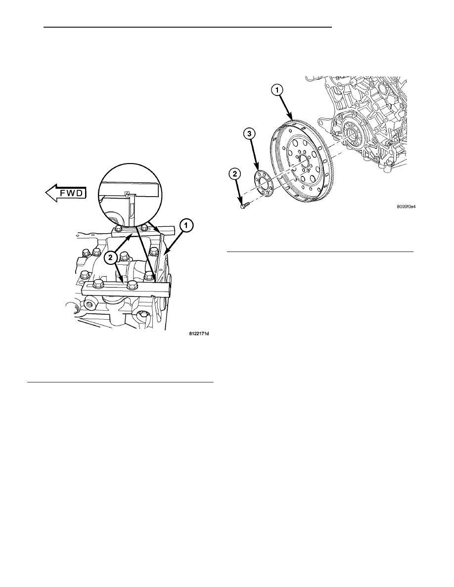
(3) Attach Special Tools 8225 to pan rail using the

oil pan fasteners (Fig. 98).

NOTE: Make sure the marking “3.5L” on Special
Tools 8225, is facing towards the cylinder block pan
rail surface (notch on tool is towards the seal
retainer).

(4) While applying firm pressure to the seal

retainer against Special Tools 8225 (Fig. 98), tighten
seal retainer screws to 12 N·m (105 in. lbs.).

(5) Install crankshaft rear oil seal. (Refer to 9 -

ENGINE/ENGINE

BLOCK/CRANKSHAFT

OIL

SEAL - REAR - INSTALLATION)

(6) Install oil pan. (Refer to 9 - ENGINE/LUBRI-

CATION/OIL PAN - INSTALLATION)

FLEX PLATE

REMOVAL

(1) Remove the transaxle (Refer to 21 - TRANS-

MISSION/TRANSAXLE/AUTOMATIC

-

41TE

-

REMOVAL).

(2) Remove flex plate attaching bolts.
(3) Remove the flex plate (Fig. 99).

INSTALLATION

(1) Position flex plate with backing plate on the

crankshaft (Fig. 99).

(2) Apply Mopar

t Lock & Seal Adhesive to the flex

plate bolts.

(3) Install flex plate bolts (Fig. 99). Tighten bolts

to 95 N·m (70 ft. lbs.).

(4) Install the transaxle (Refer to 21 - TRANSMIS-

SION/TRANSAXLE/AUTOMATIC - 41TE - INSTAL-
LATION).

PISTON & CONNECTING ROD

DESCRIPTION

The pistons are made of a high strength aluminum

alloy. Top land height has been decreased to reduce
emissions. Piston skirts are coated with a solid lubri-
cant for scuff resistance. Connecting rod is forged
steel with a fractured connecting rod cap design. The
connecting rod is also equipped with a squirt hole
and attaches to the piston with a full floating pin
retained by lock rings.

OPERATION

The piston and connecting rod assembly is the link

between the combustion force and the crankshaft.

Fig. 98 REAR CRANKSHAFT SEAL RETAINER

ALIGNMENT

1 - SEAL RETAINER
2 - SPECIAL TOOLS 8225

Fig. 99 FLEX PLATE

1 - FLEX PLATE
2 - BOLT (QTY. 8)
3 - BACKING PLATE

CS

ENGINE 3.5L

9 - 67

CRANKSHAFT REAR OIL SEAL RETAINER (Continued)

STANDARD PROCEDURE - FITTING PISTONS

The pistons are machined to two different weight

specifications and matched to rods based on weight.
All piston and rod assemblies weigh the same to
maintain engine balance.

Piston and cylinder wall must be clean and dry.

Piston diameter should be measured 90 degrees to
piston pin at size location shown in (Fig. 100). Cylin-
der bores should be measured halfway down the cyl-
inder bore and transverse to the engine crankshaft
center line (Refer to 9 - ENGINE - SPECIFICA-
TIONS). Pistons and cylinder bores should be
measured at normal room temperature, 70°F
(21°C).

REMOVAL

(1) Remove the cylinder heads (Refer to 9 -

ENGINE/CYLINDER HEAD - REMOVAL)

(2) Remove the oil pan. (Refer to 9 - ENGINE/LU-

BRICATION/OIL PAN - REMOVAL)

(3) Remove top ridge of cylinder bores with a reli-

able ridge reamer before removing pistons from cyl-
inder block. Be sure to keep tops of pistons
covered during this operation. Pistons and con-
necting rods must be removed from top of cyl-
inder

block.

When

removing

piston

and

connecting rod assemblies from the engine,
rotate crankshaft so that each connecting rod
is centered in cylinder bore.

(4) Inspect connecting rods and connecting rod

caps for cylinder identification. Identify them with a
paint mark or scribe, if necessary (Fig. 101).

(5) Remove connecting rod cap. Install protectors

on connecting rod. (Fig. 104). Push each piston and
rod assembly out of cylinder bore.

NOTE: Be careful not to nick crankshaft journals.

(6) After removal, install bearing cap on the mat-

ing rod.

INSTALLATION

(1) Install the piston rings. (Refer to 9 - ENGINE/

ENGINE

BLOCK/PISTON

RINGS

-

INSTALLA-

TION)

NOTE: The connecting rod bearing cap bolts must
be examined before reuse. If the threads are necked
down, the bolts must be replaced.

(2) Check connecting rod bolts for necking by hold-

ing a scale or straight edge against the threads. If all
threads do not contact the scale, the bolt must be
replaced (Fig. 102).

Fig. 100 Piston Measurements

Fig. 101 CONNECTING ROD TO CYLINDER

IDENTIFICATION

1 - PAINT MARK OR SCRIBE

Fig. 102 Check for Stretched Bolts

1 - STRETCHED BOLT
2 - THREADS ARE NOT STRAIGHT ON LINE
3 - THREADS ARE STRAIGHT ON LINE
4 - UNSTRETCHED BOLT

9 - 68

ENGINE 3.5L

CS

PISTON & CONNECTING ROD (Continued)

(3) Before installing pistons and connecting rod

assemblies into the bore, ensure that compression
ring gaps are staggered so that neither is in line with
oil ring rail gap (Fig. 103).

(4) Immerse the piston head and rings in clean

engine oil, slide the ring compressor over the piston
and tighten with the special wrench (Fig. 104).
Ensure position of rings does not change dur-
ing this operation.

(5) Install connecting rod bolt protectors on rod

bolts (Fig. 104).

(6) Rotate crankshaft so that the connecting rod

journal is on the center of the cylinder bore. Insert
rod and piston into cylinder bore and guide rod over
the crankshaft journal.

CAUTION: Do Not interchange piston assemblies
cylinder-to-cylinder or bank-to-bank.

Fig. 103 PISTON RING END GAP POSITION

1 - SIDE RAIL UPPER
2 - NO. 1 RING GAP
3 - PISTON PIN
4 - SIDE RAIL LOWER
5 - NO. 2 RING GAP AND SPACER EXPANDER GAP

Fig. 104 Piston and Connecting Rod

1 - “F” TOWARD FRONT OF ENGINE
2 - RING COMPRESSOR
3 - SPECIAL TOOL 8189
4 - OIL SQUIRT HOLE

CS

ENGINE 3.5L

9 - 69

PISTON & CONNECTING ROD (Continued)

(7) The arrow on top of piston must be pointing

toward front of engine (Fig. 105) and oil squirt hole
on connecting rod faces the major thrust (right) side
of the cylinder bore (Fig. 106).

(8) Tap the piston down in cylinder bore, using a

hammer handle. At the same time, guide connecting
rod into position on connecting rod journal.

(9) Install rod caps. Install cleaned and inspected

connecting rod bolts and tighten to 27 N·m (20 ft.
lbs.) Plus 1/4 turn.

(10) Install the cylinder head(s) (Refer to 9 -

ENGINE/CYLINDER HEAD - INSTALLATION)

(11) Install the oil pan. (Refer to 9 - ENGINE/LU-

BRICATION/OIL PAN - INSTALLATION)

Fig. 105 PISTON ORIENTATION

1 - ARROW FACES FRONT OF ENGINE

Fig. 106 PISTON AND CONNECTING ROD POSITIONING

1 - MAJOR THRUST SIDE OF PISTON

2 - OIL SQUIRT HOLE

9 - 70

ENGINE 3.5L

CS

PISTON & CONNECTING ROD (Continued)


Content   ..  676  677  678  679   ..