Chrysler Pacifica. Manual - part 674


  Index      Chrysler     Chrysler Pacifica - service repair manual 2005 year


Search            


Content   ..  672  673  674  675   ..


Chrysler Pacifica. Manual - part 674


The intake and exhaust rocker arms are different.

They should be identified before disassembling the
assembly (Fig. 58).

Check rocker arms for wear or damage (Fig. 59):
• Roller scuffing or wear

• Shaft bore scuffing or wear

• Swivel pad on lash adjuster missing or broken

• Rocker arm showing signs of fatigue or cracking

• Roller axle protruding from arm
Replace assembly as necessary if any rocker arms

shows signs of wear.

CAUTION: Do Not remove lash adjuster from rocker
arm assembly. Damage to the adjuster and rocker
arm will result.

ASSEMBLY

CAUTION: New dowel pins must be installed when
reassembling.

(1) Install the rocker arms, and pedestals onto the

shaft.

(2) Install dowel pins (Fig. 60). Dowel pins pass

through the pedestal into the exhaust rocker shafts.
Dowel pins should be pressed in until they bottom-
out against the rocker shaft in the pedestal.

(3) Install rocker arm and shafts. (Refer to 9 -

ENGINE/CYLINDER

HEAD/ROCKER

ARM

/

ADJUSTER ASSY - INSTALLATION)

INSTALLATION

NOTE: Rocker arm and shaft assembly can be
installed either prior to or after (preferred) cylinder
head installation.

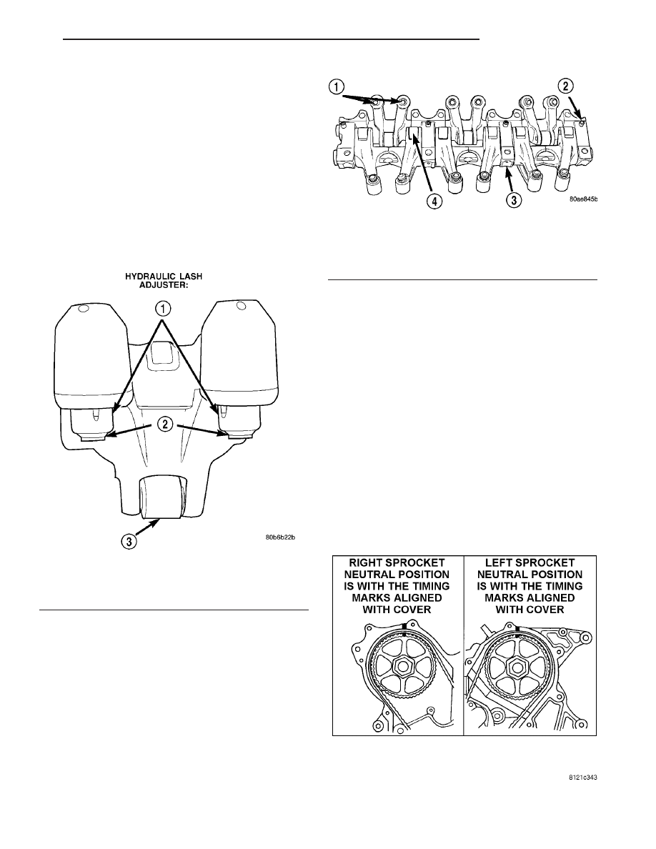
(1) Rotate camshafts to the position shown in (Fig.

61). With the camshafts in these positions the lobes
are in a neutral position (no load to the valve). This
will allow the rocker arm shaft assembly to be tight-
ened into position with little or no valve spring load
on it.

(2) Install the rocker arm and shaft assembly

making sure that the identification marks face
toward the front of engine for left head and toward
the rear of the engine for right head.

Fig. 61 CAMSHAFT GEAR TIMING MARKS

Fig. 59 Rocker Arm Assembly

1 - RETAINER
2 - SWIVEL PAD
3 - ROLLER

Fig. 60 Assemble Rocker Arms and Shaft

1 - HYDRAULIC LASH ADJUSTERS
2 - DOWEL PIN
3 - PEDESTAL
4 - ROLLER

CS

ENGINE 3.5L

9 - 51

ROCKER ARM SHAFT/ ROCKER ARM / LASH ADJUSTER (Continued)

(3) Tighten rocker arm/shaft assembly bolts in

sequence to 31 N·m (275 in. lbs.) (Fig. 62).

(4) Install cylinder head covers. (Refer to 9 -

ENGINE/CYLINDER

HEAD/CYLINDER

HEAD

COVER(S) - INSTALLATION)

TUBE -SPARK PLUG

REMOVAL

(1) Remove cylinder head cover(s). (Refer to 9 -

ENGINE/CYLINDER

HEAD/CYLINDER

HEAD

COVER(S) - REMOVAL)

(2) Using suitable locking pliers, remove the tube

from the cylinder head (Fig. 63) and discard tube.

(3) Clean area around spark plug with Mopar

t

Parts Cleaner or equivalent.

INSTALLATION

(1) Apply Mopar

t Stud and Bearing Mount to a

new tube (1) approximately 1 mm (0.039 in.) from
the end of tube, in a 3 mm (0.118 in.) wide area (Fig.
64).

(2) Install sealer end of tube(1) into the cylinder

head. Then carefully install the tube (1) using a
hardwood block and mallet. Install the tube (1) until
it is seated into the bottom of the bore.

(3) For spark plug tube (1) seal replacement,

(Refer to 9 - ENGINE/CYLINDER HEAD/CYLIN-
DER HEAD COVER(S) - REMOVAL).

(4) Install cylinder head cover(s). (Refer to 9 -

ENGINE/CYLINDER

HEAD/CYLINDER

HEAD

COVER(S) - INSTALLATION)

Fig. 62 ROCKER ARM AND CAMSHAFT ASSEMBLY

Fig. 63 Servicing Spark Plug Tubes

1 - SPARK PLUG TUBE
2 - LOCKING PLIERS

Fig. 64 CAMSHAFT, ROCKER ARM ASSEMBLY AND

CYLINDER HEAD

1 - SPARK PLUG TUBE
2 - ROCKER ARM ASSEMBLY
3 - CAMSHAFT
4 - CAMSHAFT SEAL

9 - 52

ENGINE 3.5L

CS

ROCKER ARM SHAFT/ ROCKER ARM / LASH ADJUSTER (Continued)

SEAL -VALVE STEM

REMOVAL

(1) Remove valve spring. (Refer to 9 - ENGINE/

CYLINDER HEAD/VALVE SPRINGS - REMOVAL)

(2) Remove valve stem seals by using a valve stem

seal tool (Fig. 65).

INSTALLATION

(1) The valve stem seal/valve spring seat should be

pushed firmly and squarely over the valve guide
using the valve stem as guide. Do Not Force seal
against top of guide. When installing the valve
retainer locks, compress the spring only enough to
install the locks.

CAUTION: Do not remove garter spring (2) around
the seal at the top of the valve stem seal (Fig. 66).

(2) Install valve spring. (Refer to 9 - ENGINE/

CYLINDER HEAD/VALVE SPRINGS - INSTALLA-
TION)

SPRING -VALVE

DESCRIPTION

The valve springs are made from chrome silicon

alloy wire and incorporate a “bee-hive” design. Valve
spring retainers and locks are common from valve-to-
valve. The valve spring seat is integral with the
valve stem oil seal, which incorporates a garter
spring to maintain consistent lubrication control to
the valve stem.

The valve springs are unique for intake compared

to exhaust. Both have different lengths and are
wound in opposite directions. The valve springs are
color coded, intake spring is right hand coil direction
with orange dye on the top coils, and the exhaust
spring is left hand coil direction with a yellow or
white dye on the top coils (Fig. 67).

The exhaust spring with the white dye on the top

of the coils has an increased open and closed load
when compared to the exhaust spring with the yellow
dye. A yellow and a white exhaust valve spring
should never be used on a single forked rocker arm.
Color coated exhaust springs should always be used
in pairs for a forked exhaust rocker springs.

OPERATION

The valve spring returns the valve against its seat

for a positive seal of the combustion chamber.

Fig. 65 Valve Stem Seal - Removal

1 - VALVE SEAL TOOL
2 - VALVE STEM

Fig. 66 Checking Valve Tip Height and Valve Spring

Installed Height

1 - SPRING RETAINER
2 - GARTER SPRING
3 - VALVE SPRING SEAT TOP
4 - CYLINDER HEAD SURFACE

Fig. 67 Valve Spring Identification

1 - YELLOW OR WHITE DYE
2 - ORANGE DYE

CS

ENGINE 3.5L

9 - 53

REMOVAL

REMOVAL - CYLINDER HEAD OFF

(1) Compress valve spring with valve spring com-

pressor C-3422-D and adapter 6526 (Refer to 9 -
ENGINE - SPECIAL TOOLS).

(2) Remove valve retaining locks. Release valve

spring compressor. Remove valve spring retainer and
valve spring.

(3) Remove valve stem seal assembly. (Refer to 9 -

ENGINE/CYLINDER HEAD/VALVE STEM SEALS -
REMOVAL)

REMOVAL - CYLINDER HEAD ON

(1) Disconnect negative battery cable.
(2) Remove upper intake manifold (Refer to 9 -

ENGINE/MANIFOLDS/INTAKE

MANIFOLD

-

REMOVAL).

(3) Remove cylinder head cover(s) (Refer to 9 -

ENGINE/CYLINDER

HEAD/CYLINDER

HEAD

COVER(S) - REMOVAL).

(4) Remove rocker arm and shaft assembly (Refer

to 9 - ENGINE/CYLINDER HEAD/ROCKER ARM /
ADJUSTER ASSY - REMOVAL).

(5) Remove spark plugs.
(6) Rotate the crankshaft clockwise, until the num-

ber 1 piston is at TDC (Top Dead Center) on the com-
pression stroke.

(7) With air hose attached to spark plug adapter

installed in number 1 spark plug hole, apply 620.5 to
689 kPa (90 to 100 psi) air pressure. This is to hold
valves into place while servicing components.

(8) Using Tool MD 998772A (1) with adapter 6527

(4) or equivalent, compress valve spring and remove
valve locks (5). Release tension on valve spring,
remove retainer (5) and valve spring (Refer to 9 -
ENGINE - SPECIAL TOOLS) (Fig. 68).

(9) Remove valve stem seal, if required. (Refer to 9

- ENGINE/CYLINDER HEAD/VALVE STEM SEALS
- REMOVAL)

(10) Follow the same procedure on the remaining 5

cylinders using the firing sequence 1-2-3-4-5-6. Make
sure piston is at TDC in each cylinder of the
valve spring that is being removed.

(11) Remove spark plug adapter tool.

INSPECTION

When valves have been removed for inspection,

reconditioning or replacement, valve springs should
be tested (Fig. 69). As an example; the compression
length of the spring to be tested is 38.00 mm (1.496
in.). Turn table of Tool C-647 until surface is in line
with the 38.00 mm (1.496 inches.) mark on the
threaded stud and the zero mark on the front. Place
spring over stud on the table and lift compressing
lever to set tone device. Pull on torque wrench until
ping is heard. Take reading on torque wrench at this
instant. Multiply this reading by two. This will give
the spring load at test length. Fractional measure-
ments are indicated on the table for finer adjust-
ments. Refer to Engine Specifications to obtain
specified height and allowable tensions (Refer to 9 -
ENGINE - SPECIFICATIONS). Replace springs that
do not meet specifications.

Fig. 68 VALVE SPRING REMOVAL

1 - MD 998772A
2 - SPARK PLUG TUBES
3 - CYLINDER HEAD
4 - 6527 - ADAPTOR
5 - VALVE SPRING RETAINER

Fig. 69 Testing Valve Spring

1 - SPECIAL TOOL C-647

9 - 54

ENGINE 3.5L

CS

SPRING -VALVE (Continued)


Content   ..  672  673  674  675   ..