Chrysler Pacifica. Manual - part 669


  Index      Chrysler     Chrysler Pacifica - service repair manual 2005 year


Search            


Content   ..  667  668  669  670   ..


Chrysler Pacifica. Manual - part 669


(23) Remove right exhaust manifold (Refer to 9 -

ENGINE/MANIFOLDS/EXHAUST

MANIFOLD

-

REMOVAL).

(24) Lower vehicle.
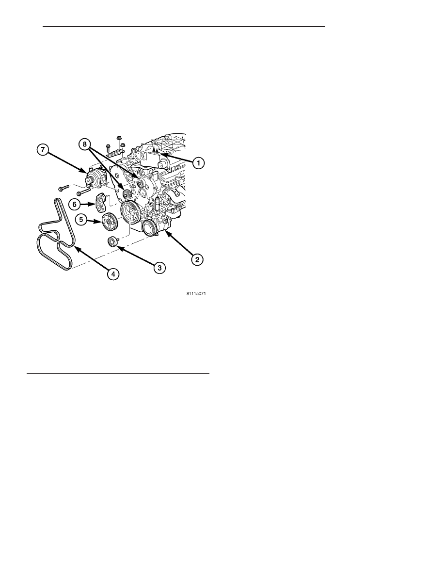
(25) Remove the upper accessory drive belt idler

pulley (Fig. 18).

(26) Remove the belt tensioner (Fig. 18).

(27) Support the engine with a block of wood and

the floor jack.

(28) Remove the upper engine mount (Refer to 9 -

ENGINE/ENGINE MOUNTING/FRONT MOUNT -
REMOVAL).

(29) Remove the power steering reservoir bolts and

set reservoir aside.

(30) Remove the remaining outer timing belt cover

bolts and cover.

(31) Rotate the engine to TDC and align timing

belt marks.

(32) Remove the timing belt tensioner and reset

the tensioner (Refer to 9 - ENGINE/VALVE TIMING/
TMNG

BELT/CHAIN

TENSIONER&PULLEY

-

REMOVAL). (Fig. 17).

(33) Remove the timing belt (Refer to 9 - ENGINE/

VALVE

TIMING/TIMING

BELT/CHAIN

AND

SPROCKETS - REMOVAL).

(34) Remove the right valve cover to cylinder head

ground strap (Fig. 20).

(35) Remove the EGR valve and tube assembly

(Fig. 20).

(36) Remove the right cylinder head cover (Fig.

20).

(37) Remove the right rocker arm assembly (Fig.

21).

(38) Remove the right rear camshaft thrust plate.
(39) Counterhold the cam gear and remove the

right cam gear retaining bolt.

Fig. 18 ACCESSORY DRIVE BELT AND PULLEYS

1 - UPPER INTAKE MANIFOLD
2 - AIR CONDITIONING COMPRESSOR
3 - IDLER PULLEY
4 - ACCESSORY DRIVE BELT
5 - POWER STEERING PULLEY
6 - ACCESSORY DRIVE BELT TENSIONER
7 - GENERATOR
8 - IDLER PULLEYS

CS

ENGINE 3.5L

9 - 31

CYLINDER HEAD(S) (Continued)

Fig. 19 TIMING GEAR MARKS

1 - RIGHT CAMSHAFT GEAR ALIGNMENT MARK

7 - LEFT CAMSHAFT GEAR

2 - RIGHT CAMSHAFT GEAR

8 - LEFT CAMSHAFT GEAR ALIGNMENT MARK

3 - CYLINDER HEAD TO INNER TIMING BELT COVER BOLTS - RIGHT

9 - CRANKSHAFT GEAR ALIGNMENT MARK

4 - TIMING BELT

10 - CRANKSHAFT GEAR

5 - WATER PUMP PULLEY

11 - TIMING BELT TENSIONER PULLEY

6 - CYLINDER HEAD TO INNER TIMING BELT COVER BOLTS - LEFT

12 - TIMING BELT TENSIONER

Fig. 20 EGR VALVE AND TUBE

1 - EGR TUBE
2 - IGNITION COIL
3 - CYLINDER HEAD COVER
4 - RIGHT EXHAUST MANIFOLD
5 - EGR VALVE

Fig. 21 CAMSHAFT, ROCKER ARM ASSEMBLY AND

CYLINDER HEAD

1 - SPARK PLUG TUBE
2 - ROCKER ARM ASSEMBLY
3 - CAMSHAFT
4 - CAMSHAFT SEAL

9 - 32

ENGINE 3.5L

CS

CYLINDER HEAD(S) (Continued)

(40) Push the camshaft out of the back of the cyl-

inder head approximately 3.5 inches and remove the
cam gear (Fig. 22).

(41) Remove the inner timing cover to cylinder

head retaining bolts.

(42) Remove the cylinder head bolts in REVERSE

of tightening sequence (Fig. 22).

NOTE: Because of clearance restrictions when
removing the right cylinder head, the front four cyl-
inder head bolts must be loosened, raised and sup-
ported with a rubber band before the cylinder head
can be removed.

(43) Remove the cylinder head (Fig. 22).

(44) Clean and inspect all mating surfaces.

LEFT CYLINDER HEAD

(1) Perform the fuel relief procedure.
(2) Disconnect the negative battery cable.
(3) Drain cooling system (Refer to 7 - COOLING -

STANDARD PROCEDURE).

(4) Remove engine cover.
(5) Remove air cleaner element housing (Refer to 9

- ENGINE/AIR INTAKE SYSTEM/AIR CLEANER
HOUSING - REMOVAL).

(6) Remove radiator close out panel.
(7) Remove radiator core support.

(8) Remove radiator fan assembly (Refer to 7 -

COOLING/ENGINE/RADIATOR FAN - REMOVAL).

(9) Disconnect the fuel line at the fuel rail.
(10) Remove the lower intake manifold (Refer to 9

-

ENGINE/MANIFOLDS/INTAKE

MANIFOLD

-

REMOVAL).

(11) Remove the left exhaust manifold (Refer to 9 -

ENGINE/MANIFOLDS/EXHAUST

MANIFOLD

-

REMOVAL).

(12) Remove the outer timing belt cover (Refer to 9

- ENGINE/VALVE TIMING/TIMING BELT / CHAIN
COVER(S) - REMOVAL).

(13) Rotate the engine to TDC and align the tim-

ing marks (Fig. 19).

(14) Remove the timing belt tensioner, timing belt,

then reset tensioner (Fig. 19).

(15) Remove the left cylinder head cover to cylin-

der head ground strap.

(16) Remove the left cylinder head cover.
(17) Remove the left rocker arm assembly.
(18) Remove the left camshaft thrust plate.
(19) Counterhold the left cam gear and remove the

cam gear retaining bolt (Fig. 19).

(20) Push the camshaft out of the back of the cyl-

inder head approximately 3.5 inches and remove the
cam gear.

(21) Remove the front timing belt housing to cylin-

der head bolts (Fig. 19).

(22) Remove the cylinder head bolts in REVERSE

of tightening sequence.

(23) Remove the cylinder head.
(24) Clean and inspect all mating surfaces.

CLEANING

To ensure engine gasket sealing, proper surface

preparation must be performed, especially with the
use of aluminum engine components and multi-layer
steel cylinder head gaskets.

NOTE: Multi-Layer Steel (MLS) head gaskets require
a scratch free sealing surface.

Remove all gasket material from cylinder head and

block (Refer to 9 - ENGINE - STANDARD PROCE-
DURE). Be careful not to gouge or scratch the alumi-
num head sealing surface.

Clean all engine oil passages.

INSPECTION

(1) Before cleaning, check for leaks, damage and

cracks.

(2) Clean cylinder head and oil passages.
(3) Check cylinder head for flatness (Fig. 23).
(4) Cylinder head must be flat within:
• Standard dimension = less than 0.05 mm (0.002

inch.)

• Service Limit = 0.2 mm (0.008 inch.)

Fig. 22 RIGHT CYLINDER HEAD

1 - INNER TIMING BELT COVER
2 - CYLINDER HEAD BOLTS
3 - RUBBER BANDS
4 - SPARK PLUG TUBE
5 - CAMSHAFT

CS

ENGINE 3.5L

9 - 33

CYLINDER HEAD(S) (Continued)

• Grinding Limit = Maximum of 0.2 mm (0.008

inch.) is permitted.

CAUTION: 0.20 mm (0.008 in.) MAX is a combined
total dimension of the stock removal limit from cyl-
inder head and block top surface (Deck) together.

INSTALLATION - CYLINDER HEAD(S)

RIGHT CYLINDER HEAD

CAUTION: THE CYLINDER HEAD GASKETS ARE
NOT

INTERCHANGEABLE

BETWEEN

CYLINDER

HEADS AND ARE CLEARLY MARKED RIGHT OR
LEFT.

The cylinder head bolts are tightened using a

torque plus angle procedure. The bolts must be
examined BEFORE reuse. If the threads are
necked down the bolts must be replaced (Fig.
24).
.

Necking can be checked by holding a scale or

straight edge against the threads. If all the threads
do not contact the scale the bolt must be replaced
(Fig. 24).

CAUTION: When cleaning cylinder head and cylin-
der block surfaces, DO NOT use a metal scraper
because the surfaces could be cut or ground. Use
ONLY a wooden or plastic scraper (Refer to 9 -
ENGINE - STANDARD PROCEDURE - ENGINE GAS-
KET SURFACE PREPARATION).

(1) Clean sealing surfaces of cylinder head and

block.

CAUTION: Ensure that the correct head gaskets are
used and are oriented correctly on cylinder block.

(2) Install

head

gasket

over

locating

dowels.

Ensure the gasket is installed on the correct side of
engine.

NOTE: Before installing the cylinder head bolts,
lubricate the threads with engine oil.

(3) Insert the front four cylinder head bolts into

the cylinder head. Pull the bolts up to the top of their
travel and retain with rubber bands.

(4) Install the cylinder head over locating dowels

and finger tighten the head bolts.

(5) Tighten the cylinder head bolts in the sequence

shown in (Fig. 25). Using the 4 step torque-turn
method, tighten according to the following torque val-
ues:

• Step 1: All to 61 N·m (45 ft. lbs.)

• Step 2: All to 88 N·m (65 ft. lbs.)

• Step 3: All (again) to 88 N·m (65 ft. lbs.)

• Step 4: + 90° Turn Do not use a torque

wrench for this step.

(6) Bolt torque after 90° turn should be over 122

N·m (90 ft. lbs.) in the tightening direction. If not,
replace the bolt.

(7) Install the inner timing cover to cylinder head

bolts. Tighten bolts to 54 N·m (40 lbs.ft.).

Fig. 23 Checking Cylinder Head Flatness

Fig. 24 Check for Stretched Bolts

1 - STRETCHED BOLT
2 - THREADS ARE NOT STRAIGHT ON LINE
3 - THREADS ARE STRAIGHT ON LINE
4 - UNSTRETCHED BOLT

Fig. 25 Cylinder Head Bolt Tightening Sequence

9 - 34

ENGINE 3.5L

CS

CYLINDER HEAD(S) (Continued)


Content   ..  667  668  669  670   ..