Chrysler Pacifica. Manual - part 444


  Index      Chrysler     Chrysler Pacifica - service repair manual 2005 year


Search            


Content   ..  442  443  444  445   ..


Chrysler Pacifica. Manual - part 444


STEADY STATE, HIGH SPEED, NO WHEEL SLIP

The roller cage positions the rollers on the input

shaft flats during low and high speed overrunning
and during initial BOC lockup. The roller cage is
rotating at input shaft (propeller shaft) speed at all
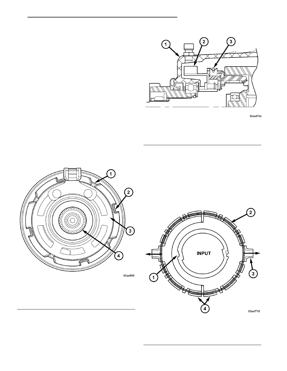
times. At low speeds, the friction shoes (Fig. 44) are
pressed against the friction ground via the garter
spring (Fig. 45), creating a drag force on the roller
cage. The drag force positions the cage, which in turn
positions the rollers to one side of the flat. The direc-
tion of this drag force (position of the roller) is depen-
dent

on

the

input

(propeller

shaft)

rotational

direction. Since the rollers are always in contact with
the outer race, due to centrifugal forces, the rollers
want to follow the outer race due to drag. During
overrunning operation, the outer race is rotating
faster than the input; causing the rollers to want to
traverse the flat from one side to the other. During
low speeds, the brake shoes counteract this effect. To
avoid excessive wear, the ground shoes are designed
to lift off from the friction ground due to centrifugal
forces at higher rotational speeds.

To keep the rollers in the overrunning position and

avoid undesired

9high speed lockup9, a high speed

latch (Fig. 46) positions the cage before the ground
shoes lift off. A further explanation of the high speed
effects follows as well. Utilizing only the friction
shoes approach means that at high speed the
required ground shoe drag torque would cause exces-

sive brake shoe wear or the roller will begin to
migrate to the opposite side of the flat due to the
drag force of the outer race. This would result in sys-
tem lock-up. (Fig. 47) shows the BOC as it crosses
the speed where the brake shoe force is overcome by
the roller drag on the outer race. Notice that the
roller is locking up on the opposite side of the flat
and the cage supplies no force on the rollers.

Fig. 44 Front View of BOC

1 - GARTER SPRING
2 - FRICTION BRAKE SHOES
3 - FRICTION GROUND CONNECTED TO GROUND TAB
4 - INPUT SHAFT

Fig. 45 Location of the Grounding Element

1 - DIFFERENTIAL HOUSING
2 - GROUND TAB
3 - GARTER SPRING

Fig. 46 BOC High Speed Latch (Not Engaged)

1 - TOOTH (TWO PLACES)
2 - GARTER SPRING
3 - TABS AT BOTH ENDS FIT INTO SLOTS IN CAGE
4 - TWO PART DESIGN

CS

REAR DRIVELINE MODULE

3 - 45

BI-DIRECTIONAL OVERRUNNING CLUTCH (Continued)

This lock-up is not desired, and requires the use of

another mechanism to prevent the lock-up. The
device that prevents undesired high-speed lock-up is
called a

9high speed latch9.

Similar to the friction shoes, the two-piece high-

speed latch will separate from each other at high
rotational speeds due to centrifugal effects. (Fig. 48)
shows the high speed latch engaged. The gap

9x9

increases with speed, eventually locking into one of
the slots in the BOC shaft. When the high-speed
latch is activated (propeller shaft speed reaches X
amount), the cage is partially fixed, and cannot lock
on the wrong side of the flat as shown (Fig. 47). The
high speed latch is a one way device and does not
prevent high-speed lockup in the reverse direction. At
high speeds, the BOC provides the same function as
low speeds, transferring torque to the viscous coupler
only when front wheel slip overcomes the axle ratio
offset.

At high speed, the rollers are forced outward to the

outer race because of centrifugal force. At high
speeds, the friction shoes can no longer prevent lock-
up. When the teeth on the high-speed latch engage
into the input shaft, it keeps the rollers centered
above the flats because the tabs on the latch are
locked into the cage. (Fig. 49) shows the roller config-
uration with the High-Speed Latch engaged.

Fig. 47 BOC Operation During High Speed Lock-up Without High Speed Latch

Fig. 48 High Speed Latch Engaged

1 - CAGE FORCE EXERTED BY ROLLERS AT HIGH SPEED

3 - 46

REAR DRIVELINE MODULE

CS

BI-DIRECTIONAL OVERRUNNING CLUTCH (Continued)

On the BOC shaft, the high speed latch teeth lock

up in the grooved areas, shown in (Fig. 50), when the
turning speed reaches the critical value. (Fig. 50)
also shows the outer race/viscous coupler. Notice the
surface (outer race) the rollers mate against when
transferring torque.

DIFFERENTIAL ASSEMBLY

DESCRIPTION

The differential gear system divides the torque

between the axle shafts. It allows the axle shafts to
rotate at different speeds when turning corners.

Each differential side gear is splined to an axle

shaft. The pinion gears are mounted on a pinion
mate shaft and are free to rotate on the shaft. The
pinion gear is fitted in a bore in the differential case
and is positioned at a right angle to the axle shafts.

OPERATION

In operation, power flow occurs as follows:
• The pinion gear rotates the ring gear

• The ring gear (bolted to the differential case)

rotates the case

• The differential pinion gears (mounted on the

pinion mate shaft in the case) rotate the side gears

• The side gears (splined to the axle shafts) rotate

the shafts

During straight-ahead driving, the differential pin-

ion gears do not rotate on the pinion mate shaft. This
occurs because input torque applied to the gears is
divided and distributed equally between the two side
gears. As a result, the pinion gears revolve with the
pinion mate shaft but do not rotate around it (Fig.
51).

Fig. 49 BOC Operation at High Speed with High

Speed Latch

Fig. 50 BOC Input Shaft

1 - GROOVED AREA (2 LOCATIONS)
2 - ROLLER MATING SURFACE

Fig. 51 Differential Operation—Straight Ahead

Driving

1 - IN STRAIGHT AHEAD DRIVING EACH WHEEL ROTATES AT
100% OF CASE SPEED
2 - PINION GEAR
3 - SIDE GEAR
4 - PINION GEARS ROTATE WITH CASE

CS

REAR DRIVELINE MODULE

3 - 47

BI-DIRECTIONAL OVERRUNNING CLUTCH (Continued)

When turning corners, the outside wheel must

travel a greater distance than the inside wheel to
complete a turn. The difference must be compensated
for to prevent the tires from scuffing and skidding
through turns. To accomplish this, the differential
allows the axle shafts to turn at unequal speeds (Fig.
52). In this instance, the input torque applied to the
pinion gears is not divided equally. The pinion gears
now rotate around the pinion mate shaft in opposite
directions. This allows the side gear and axle shaft
attached to the outside wheel to rotate at a faster
speed.

FLUID - DIFFERENTIAL
ASSEMBLY

STANDARD PROCEDURE - DIFFERENTIAL
ASSEMBLY FLUID CHANGE

The drain plug (Fig. 53) for the differential assem-

bly is located in the bottom of the differential assem-
bly case, toward the rear of the unit.

The fill plug (Fig. 54) for the differential assembly

is located on the rear of the assembly case.

The correct fill level is to the bottom of the fill plug

hole. Be sure the vehicle is on a level surface, or is
hoisted in a level manner, in order to obtain the cor-
rect fill level.

(1) Raise the vehicle on a hoist.
(2) Position a drain pan under the differential

drain plug (Fig. 53).

(3) Remove the drain plug and allow the fluid to

drain into the pan.

(4) Install the drain plug and torque to 35 N·m (26

ft. lbs.).

(5) Re-position the drain pan under the differential

fill plug.

(6) Remove the differential fill plug (Fig. 54).
(7) Using a suction gun (Fig. 55) or equivalent, fill

the differential assembly with 0.7 L (0.74 Qts.) of
Mopar

t Gear and Axle Lubricant (75W-90).

Fig. 52 Differential Operation—On Turns

1 - PINION GEARS ROTATE ON PINION SHAFT

Fig. 53 Differential Drain Plug

1 - DIFFERENTIAL DRAIN PLUG

Fig. 54 Differential Fill Plug

1 - DIFFERENTIAL FILL PLUG

3 - 48

REAR DRIVELINE MODULE

CS

DIFFERENTIAL ASSEMBLY (Continued)


Content   ..  442  443  444  445   ..