Chrysler New Yorker. Manual - part 303


  Index      Chrysler     Chrysler New Yorker - service repair manual 1997-1999 year


Search            


Content   ..  301  302  303  304   ..


Chrysler New Yorker. Manual - part 303


CAUTION: Always use a new transfer shaft nut. Do
not reuse old transfer shaft nut.

(44) Install a new transfer shaft nut (Fig. 331).

Tighten nut to 271 N·m (200 ft. lbs.). Use special
tools 6497 holder and 6498 shaft socket to tighten
nut.

CAUTION: Failure to set the transfer shaft turning
torque correctly may cause transfer shaft bearings
or seals to fail. Be sure transfer shaft does not have
end play. If end play exists, install a thinner preload
shim.

(45) Check the turning torque of the transfer shaft

using a torque wrench (Fig. 332). The turning torque

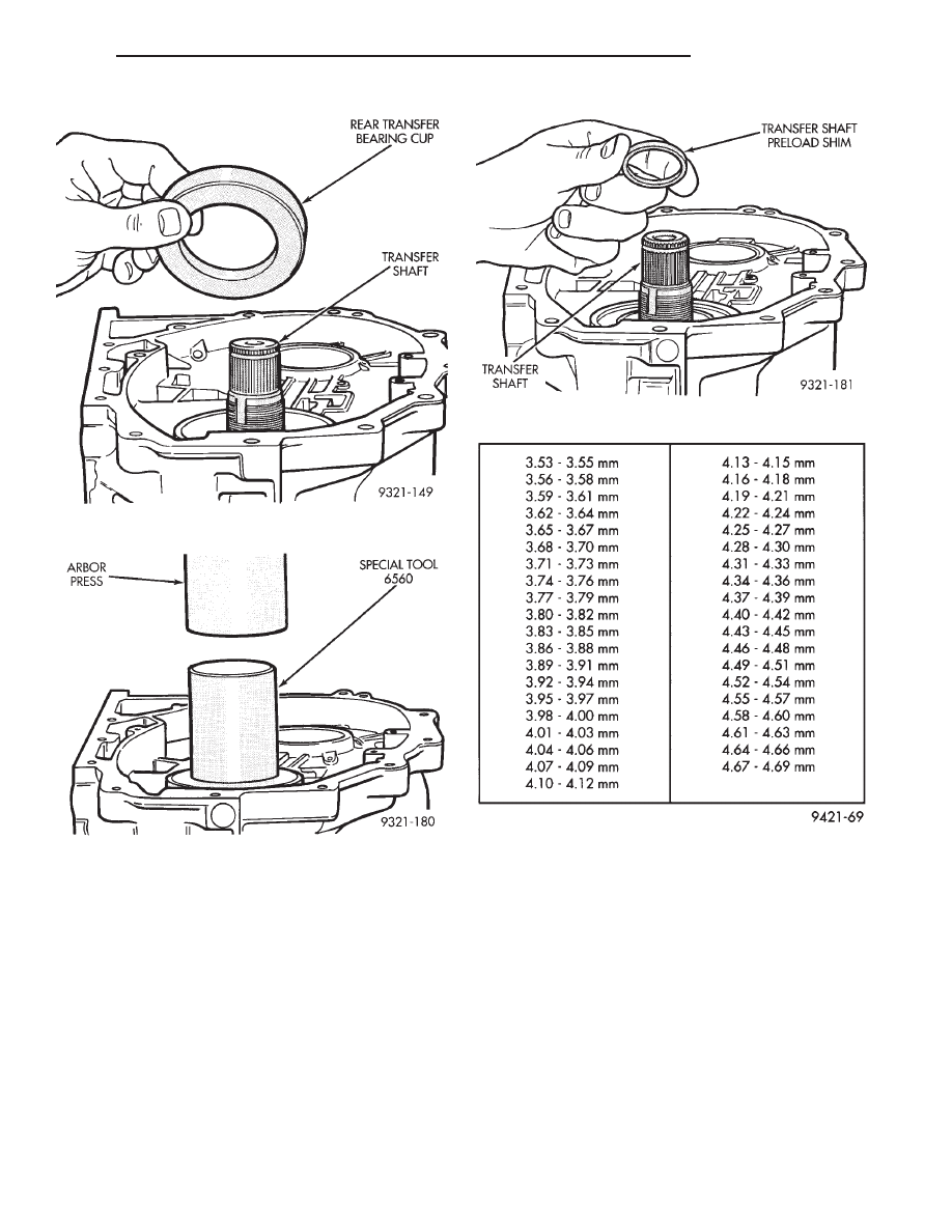
Fig. 328 Rear Transfer Bearing Cup

Fig. 329 Rear Transfer Shaft Cup Installation

Fig. 330 Transfer Preload Shim Installation

Transfer Shaft Rear Shim Chart

300M

TRANSAXLE

21 - 85

DISASSEMBLY AND ASSEMBLY (Continued)

should be 0.5 to 1.3 N·m (5 to 12 in. lbs.). If the turn-
ing torque is too high, install a thicker transfer shaft
preload shim. If the turning torque is too low, install
a thinner transfer shaft preload shim.

CAUTION: A press and special tool 6589 must be
used when staking the transfer shaft nut. Do not use
a hammer and the special tool to stake nut. If a ham-
mer is used; seal, bearing, and/or tool damage may
result. Also the stake will not be seated against the
shaft correctly. This will allow the nut to loosen.

(46) After the correct turning torque is obtained,

use special tool 6589 to stake the new transfer shaft
nut (Fig. 333). Be sure that the tool arms line up
with slots in the transfer shaft. Use a press with the
special tool to make the stakes in the nut.

CAUTION: Failure to stake the transfer shaft nut
correctly may allow the nut to loosen during trans-
axle operation. This will cause transaxle failure.

(47) At this point the transfer shaft, new oil seals,

pinion depth and transfer shaft preload have been
set. The following steps will set the backlash between
the transfer shaft and the ring gear.

(48) If the carrier requires reconditioning, refer to

Differential Carrier Recondition.

(49) Install vent baffle. Apply sealer as shown in

(Fig. 335).

(50) Install new inner adjuster O-ring. Lube inner

adjuster threads and O-ring. Then install inner
adjuster flush with differential side of case.

(51) Install differential assembly (with ring gear

attached) into transaxle case (Fig. 336).

Fig. 333 Staking New Nuts

Fig. 334 Correctly Staked Nut

Fig. 331 Transfer Shaft Nut Installation

Fig. 332 Checking Turning Torque

21 - 86

TRANSAXLE

300M

DISASSEMBLY AND ASSEMBLY (Continued)

(52) Transfer shaft to ring gear backlash should be

0.006

9 to 0.0099 thousands of an inch. To get the

backlash close enough to measure, perform the fol-
lowing steps. Hold the transfer shaft with one hand
and rock the ring gear back and forth (Fig. 337). You
should feel some backlash between the gears. If no
backlash is felt use special tool 6502B to turn the
inner adjuster so that it raises the differential
assembly. This will increase backlash. If there is too
much backlash, use special tool 6502B to turn the
inner adjuster so that it lowers the differential
assembly. This will decrease backlash. Recheck the
backlash after each adjustment.

(53) Apply a 1/8 inch bead of sealant to differential

cover flange. Then install differential cover with seal-
ant (Fig. 338) and tighten cover bolts.

(54) Install seal protector (special tool 6591) on

shaft (Fig. 339).

CAUTION: Lube threads and O-ring on adjuster
before installing. Failure to due so will result in
thread damage to the adjuster and differential
cover.

(55) Install outer adjuster with new O-ring (Fig.

340). Torque the outer adjuster (special tool 6503) to
the torque reading recorded in Step 31. Then seat
bearings by turning differential three or four revolu-
tions in both directions. Tighten adjuster a second
time to same torque recorded in Step 31. Again
reseat bearings. Repeat this sequence until correct
adjuster torque is maintained.

Fig. 337 Rocking Ring Gear Back and Forth

Fig. 338 Differential Cover Installation

Fig. 335 Baffle Installation

Fig. 336 Differential Assembly Installation

300M

TRANSAXLE

21 - 87

DISASSEMBLY AND ASSEMBLY (Continued)

(56) To check and/or adjust backlash, remove the

inspection plug from the top of the differential.
Install dial indicator as shown in (Fig. 341). The tip
of the dial indicator must be perpendicular against
one of the ring gear teeth. Hold transfer shaft with
locking pliers. Move ring gear back and forth with
special tool 6548. Read the amount of backlash with
dial indicator. Backlash should be 0.006

9 to 0.0099

thousands of an inch.

(57) If there is too much backlash, loosen the outer

adjuster with special tool 6503. Then turn the inner
adjuster so that it moves away from the ring
gear. 
After adjusting the inner adjuster, retighten
the outer adjuster to the torque recorded in Step 30.
The inner adjuster should be turned in small incre-
ments.

(58) If there is not enough backlash, loosen the

outer adjuster with special tool 6503. Then turn the
inner adjuster so that it moves towards the ring
gear. 
After adjusting the inner adjuster, retighten
the outer adjuster to the torque recorded in Step 30.
The inner adjuster should be turned in small incre-
ments.

(59) Once backlash is within specifications, recheck

backlash in four spots on the ring gear 90 degrees
apart. All four readings should be within specifica-
tions.

(60) Install inner and outer adjuster locking brack-

ets.

(61) Install new inspection plug. Use a wooden

block to tap inspection plug into place.

(62) It is easier to fill the differential prior to

installing the transaxle back into the vehicle. The
differential holds 32 ounces of fluid.

DIFFERENTIAL CARRIER-RECONDITION

CAUTION: Ring gear bolts are not reusable. When
reassembling use new bolts.

NOTE: Mark ring gear location, if reusing ring gear.

NOTE: When

reassembling

differential,

line

up

notches on side of carrier.

Fig. 339 Seal Protector

Fig. 340 Outer Adjuster Installation

Fig. 341 Dial Indicator Installation

Fig. 342 Remove Ring Gear Bolts

21 - 88

TRANSAXLE

300M

DISASSEMBLY AND ASSEMBLY (Continued)


Content   ..  301  302  303  304   ..