Chrysler New Yorker. Manual - part 210
ROCKER ARMS
REMOVAL
(1) Remove cylinder head cover(s) using procedure
outlined in this section.
CAUTION: Always rotate engine by turning the
crankshaft. Failure to do so will result in valve
and/or piston damage.
(2) Rotate engine until the cam lobe is on its base
circle (heel), on the rocker arm being removed.
CAUTION: Depress valve spring only enough to
remove rocker arm.
(3) Using Special Tools 8215 and 8216 Adaptor,
depress valve spring only enough to release tension
on rocker arm (Fig. 42).
(4) Remove rocker arm from cylinder head.
CAUTION: If rocker arms are to be reused, identify
position of rocker arms for reassembly in their orig-
inal positions.
(5) Repeat procedure for each rocker arm being
removed.
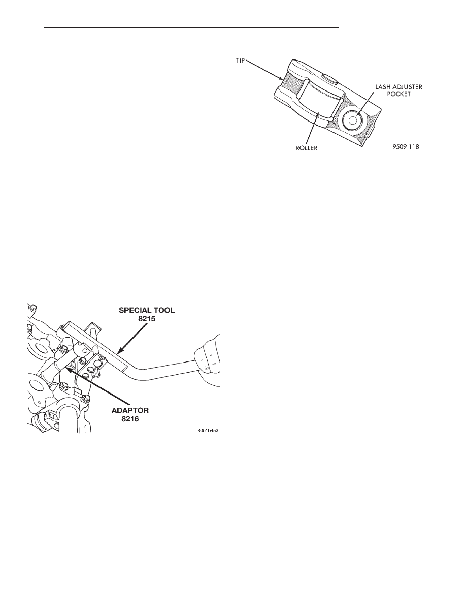
INSPECTION
Inspect the rocker arm for wear or damage (Fig.
43). Replace as necessary.
INSTALLATION
(1) Lubricate with rocker arms with clean engine
oil before installation.
(2) Rotate engine until cam lobe is on its base cir-
cle (heel) of rocker arm being installed.
(3) Using Special Tools 8215 and 8216 Adaptor,
depress valve spring only enough to install rocker
arm (Fig. 42).
(4) Install rocker arm in original position (if
reused) over valve and lash adjuster. Release tension
on valve spring.
NOTE:
Inspect rocker arm for proper engagement
into lash adjuster and valve tip.
(5) Repeat procedure for each rocker arm being
installed.
(6) Install cylinder head cover(s) using procedure
outlined in this section.
HYDRAULIC LASH ADJUSTER
REMOVAL
(1) Remove cylinder head cover(s). Refer to proce-
dure outlined in this section.
(2) Remove rocker arm(s). Refer to procedure out-
lined in this section.
CAUTION: If lash adjusters and rocker arms are to
be reused, always mark position for reassembly in
their original positions.
(3) Remove lash adjuster(s).
INSTALLATION
(1) Install hydraulic lash adjuster making sure
adjusters are at least partially full of oil. This can be
verified by little or no plunger travel when lash
adjuster is depressed.
(2) Install rocker arm(s). Refer to procedure out-
lined in this section.
(3) Install cylinder head cover(s).
VALVE STEM SEALS OR VALVE SPRINGS—IN
VEHICLE
REMOVAL
(1) Perform fuel system pressure release procedure
before attempting any repairs. Refer to Group 14,
Fuel System for procedure.
(2) Disconnect negative cable from remote jumper
terminal.
Fig. 42 Rocker Arm—Removal/Installation
Fig. 43 Rocker Arm
LH
2.7L ENGINE
9 - 35
REMOVAL AND INSTALLATION (Continued)