Chrysler New Yorker. Manual - part 209


  Index      Chrysler     Chrysler New Yorker - service repair manual 1997-1999 year


Search            


Content   ..  207  208  209  210   ..


Chrysler New Yorker. Manual - part 209


NOTE: Do not reuse V-Band clamps.

(22) Install new V-Band clamps at exhaust mani-

folds and tighten to 11 N·m (100 in. lbs.).

(23) Install catalytic converter down pipe front and

rear supports.

(24) Install

air

conditioning

compressor

and

tighten fasteners to 28 N·m (250 in. lbs.)

(25) Install power steering pump and tighten fas-

teners to 28 N·m (250 in. lbs.).

(26) Install radiator.
(27) Connect transaxle cooler lines to radiator.
(28) Attach A/C condenser to radiator.
(29) Install lower radiator hose.
(30) Install upper radiator hose.
(31) Install A/C and accessory drive belts. Refer to

Group 07, Cooling System for procedure.

(32) Install cooling fan module.
(33) Refill cooling system. Refer to Group 07, Cool-

ing System for procedure.

(34) Fill engine with proper amount of oil.
(35) Connect hood release cable to hood latch and

install upper radiator crossmember.

(36) Install air cleaner and air inlet hose.
(37) Install cowl support.
(38) Install right and left cowl covers.
(39) Install both wiper arms.
(40) Install hood.
(41) Connect negative cable to remote jumper ter-

minal at right strut tower.

CRANKSHAFT DAMPER

REMOVAL

(1) Remove upper radiator crossmember. Refer to

Group 23, Body for procedure.

(2) Remove fan module. Refer to Group 07, Cooling

System for procedure.

(3) Remove accessory drive belt and air condition-

ing belt. Refer to Group 07, Cooling System for pro-
cedure.

(4) Remove damper center bolt while holding the

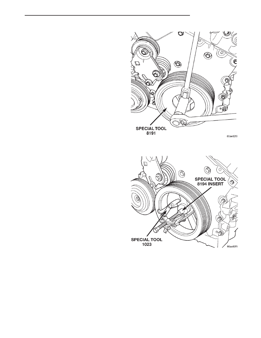
damper with Special Tool 8191 (Fig. 30).

CAUTION: Before removing damper, verify that A/C
belt tensioner is not contacting the damper, as
damage could occur to tensioner, timing chain
cover, and/or damper.

(5) Remove damper by using Special Tools 8194

Insert and 1023 Three Jaw Puller (Fig. 31).

INSTALLATION

(1) Install damper using Special Tools 8179 Screw,

with Nut and Thrust Bearing from 6792, and 6792-1
Installer (Fig. 32).

(2) Install damper center bolt. Tighten center bolt

while holding the damper with Special Tool 8191 to
170 N·m (125 ft. lbs.) (Fig. 30).

(3) Install air conditioning and accessory drive

belts. Refer to Group 07, Cooling System for proce-
dures.

(4) Install cooling fan module and connect electri-

cal connector.

(5) Install upper radiator crossmember.

Fig. 30 Crankshaft Damper Center Bolt—Removal

and Installation

Fig. 31 Crankshaft Damper—Removal

LH

2.7L ENGINE

9 - 31

REMOVAL AND INSTALLATION (Continued)

CYLINDER HEAD COVERS

REMOVAL

(1) Remove upper intake manifold. Refer to Group

11, Exhaust System and Intake Manifold

(2) Remove

electrical

connectors

from

ignition

coils.

(3) Remove ground strap from right cylinder head.
(4) Disconnect

electrical

and

vacuum

harness

retaining clips from cylinder head cover studs.

(5) Remove fasteners attaching ignition coil capac-

itors.

(6) Remove fastener attaching right and left side

support brackets for upper intake manifold (Fig. 33).

(7) Loosen all cylinder head cover attaching bolts

(Fig. 34).

NOTE: Cylinder head cover attaching bolts are cap-
tured to the cover.

(8) Remove cylinder head covers.

INSTALLATION

(1) Clean cylinder head cover and both sealing sur-

faces. Inspect and replace gaskets as necessary (Fig.
35).

(2) Install cylinder head covers and hand start all

fasteners. Verify that all double-ended studs are in
the correct locations as shown in (Fig. 34).

(3) Tighten cylinder head cover attaching bolts and

double-ended studs to 12 N·m (105 in. lbs.).

(4) Connect all electrical connectors and harness

clips.

(5) Install ignition coil capacitors and fasteners.
(6) Install right and left side support brackets for

the upper intake manifold (Fig. 33). Tighten fasten-
ers only finger tight at this time.

(7) Install upper intake manifold. Refer to Group

11, Exhaust System and Intake Manifold for proce-
dure.

CAMSHAFTS

REMOVAL

(1) Remove the primary timing chain. Refer to pro-

cedure outlined in this section.

(2) Remove secondary chain tensioner mounting

bolts.

NOTE: Camshaft bearing caps have been marked
during engine manufacturing. For example, number
one exhaust camshaft bearing is marked “1E”

Fig. 32 Crankshaft Damper—Installation

Fig. 33 Intake Manifold Side Support Brackets—Left

Side

Fig. 34 Cylinder Head Covers

9 - 32

2.7L ENGINE

LH

REMOVAL AND INSTALLATION (Continued)

(3) Slowly loosen camshaft bearing cap bolts in

reverse order of installation (Fig. 36).

(4) Remove camshaft bearing caps.
(5) Remove camshafts, secondary chain, and ten-

sioner together as an assembly.

(6) Remove tensioner and camshaft chain from

camshafts.

(7) Inspect

camshafts.

Refer

to

Cleaning

and

Inspection in the Section.

INSTALLATION

CAUTION: When the timing chain is removed and
the cylinder heads are installed, DO NOT rotate the
camshafts or crankshaft without first locating the
proper crankshaft position. Failure to do so will
result in valve and/or piston damage.

(1) Assemble camshaft chain on the cams. Ensure

that plated links are facing toward the front. Align
the plated links to the dot on the camshaft sprockets
(Fig. 40).

NOTE: Two styles of camshaft (Secondary) chain
tensioners will be used; the Early Build tensioners

will separate into subcomponents, the Later Build
tensioners will not.

(2) If camshaft chain tensioner is already in the

compressed and locked position, proceed to step (4).

(3) When the camshaft chain tensioner is removed,

it is necessary to compress and lock the tensioner
using the following procedures:

EARLY BUILD

• Separate the tensioner cylinder from tensioner

housing (Fig. 37).

• Carefully drain oil from housing using care not

to remove the internal tensioner components.

• Assemble plunger to housing (Fig. 37).

• Using hand pressure, compress tensioner and

lock using a fabricated lock pin or the equivalent
(Fig. 38).

LATE BUILD

• Place tensioner into a soft jaw vise (Fig. 39).

• SLOWLY compress tensioner until fabricated

lock pin or the equivalent can be inserted into the
locking holes.

Fig. 35 Cylinder Head Cover Gasket and Spark Plug

Seals

Fig. 36 Camshaft Bearing Cap Tightening Sequence

Fig. 37 Camshaft (Secondary) Chain Tensioner

LH

2.7L ENGINE

9 - 33

REMOVAL AND INSTALLATION (Continued)

• Remove compressed and locked tensioner from

the vise.

(4) Insert the compressed and locked camshaft

chain tensioner in-between the camshafts and chain.

(5) Rotate the cams so that the plated links and

dots are facing the 12:00 O’clock position (Fig. 40).

(6) Install cams to cylinder head. Ensure that

rocker arms are correctly seated and in proper posi-
tions.

(7) Install camshaft bearing caps. Ensure that

bearing caps are installed in same position as
removed.

(8) Tighten cam bearing cap bolts gradually in

sequence shown in (Fig. 36) to 12 N·m (105 in. lbs.).

(9) Install secondary chain tensioner bolts and

tighten to 12 N·m (105 in. lbs.).

(10) Remove locking pin from secondary tension-

ers.

(11) Measure camshafts end play by mounting a

dial indicator to a stationary point on cylinder head.
Locate the probe perpendicular against the end of
camshaft being checked. Move camshaft all the way
to the rear of its travel. Zero the dial indicator. Move
camshaft forward to limits of travel and read the dial
indicator (Fig. 41).

(12) Install primary timing chain. Refer to proce-

dure outlined in this section.

Fig. 38 Locking Camshaft (Secondary) Chain

Tensioner—Early Build

Fig. 39 Locking Camshaft (Secondary) Chain

Tensioner—Late Build

Fig. 40 Camshaft Chain Timing

Fig. 41 Camshaft End Play Measuring

9 - 34

2.7L ENGINE

LH

REMOVAL AND INSTALLATION (Continued)


Content   ..  207  208  209  210   ..