Chrysler New Yorker. Manual - part 43
ENGINE THERMOSTAT
The thermostat is operated by a wax filled con-
tainer (pellet) which is sealed so that when heated to
a predetermined temperature, the wax expands
enough to overcome the closing spring and water
pump pressure, which forces the valve to open. Cool-
ant leakage into the pellet will cause a thermostat to
fail open. Do not attempt to free up a thermostat
with a screwdriver.
The open too soon type failure mode is included in
the on-board diagnosis. The check engine light will
not be lit by an open too soon condition. If it has
failed open, a DTC diagnostic trouble code will be
set. Do not change a thermostat for lack of heat by
gauge or heater performance, unless a code is
present, see diagnosis for other probable causes. Fail-
ing shut is the normal long term mode of failure, and
normally, only on high mileage vehicles. The temper-
ature gauge will indicate this, Refer to diagnosis in
this section.
WATER PUMP DIAGNOSIS
A quick test to tell whether or not the pump is
working is to see if the heater warms properly. A
defective pump will not be able to circulate heated
coolant through the long heater hose. The water
pump on all models can be replaced without
discharging the air conditioning system.
NOTE: It is normal for the water pump to weep a
small amount of coolant from the weep hole (black
stain on water pump body). Do not replace the
water pump if this condition exists. Replace the
water pump if a heavy deposit or a steady flow of
green/brown engine coolant is evident on water
pump body from the weep hole (shaft seal failure).
Be sure to perform a thorough analysis before
replacing water pump.
RADIATOR FAN CONTROL
Fan control is accomplished two ways. A pressure
transducer on the air conditioning compressor dis-
charge line sends a signal to the Powertrain Control
Module (PCM) which will activate both fans if neces-
sary. In addition to this control, the fan is turned on
based on coolant temperature sensor output to the
(PCM). The PCM switches the fans on through the
fan relays. Refer to Wiring Diagrams Manual for cir-
cuit and diagnostics.
Switching through the (PCM) provides fan control
for the following conditions.
• Regardless of coolant temperature the fan will
not run during cranking until the engine starts.
• Fans will run in accordance with following oper-
ation charts.
RADIATOR COOLANT FLOW
To determine whether coolant is flowing through
the cooling system, use the following procedure:
• If engine is cold, idle engine until normal oper-
ating temperature is reached. If the upper radiator
hose is hot, coolant is circulating.
WARNING:
DO NOT REMOVE COOLANT PRES-
SURE CAP WITH THE SYSTEM HOT AND UNDER
PRESSURE
BECAUSE
SERIOUS
BURNS
FROM
COOLANT CAN OCCUR.
ELECTRIC FAN MOTOR
Refer to Power Train Diagnostic Manual for proce-
dure.
TESTING SYSTEM FOR LEAKS
With engine not running, wipe the coolant bottle
neck sealing seat clean.
Attach a radiator pressure tester to the coolant
bottle, as shown in (Fig. 12) and apply 104 kPa (15
psi) pressure. If the pressure drops more than 2 psi
in 2 minutes inspect all points for external leaks.
All hoses, radiator and heater, should be moved
while at 15 psi since some leaks occur while driving
due to engine rock, etc. If the cooling system will not
pressurize easily and there is no coolant leaks, the
cooling system is only partially filled. Refer to filling
procedure in this section.
If there are no external leaks after the gauge dial
shows a drop in pressure, detach the tester. Start
engine and run the engine to normal operating tem-
perature in order to open the thermostat and allow
the coolant to expand. Reattach the tester. If the nee-
dle on the dial fluctuates it indicates a combustion
leak, usually a head gasket leak.
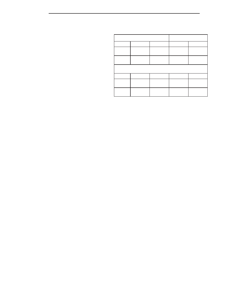
RADIATOR FAN OPERATION —ALL ENGINES
Radiator Fan Control
A/C Pressure
A/C Off
Low
High
Fan On:
110°C
(230°F)
113°C
(235°F)
Fan Off:
104°C
(219°F *)
111°C
(231°F)
*109°C (228°F) @ Vehicle speed greater than
12.8 Kmh (8 mph).
A/C On
Low
High
Low
High
Fan On:
105°C
(221°F)
110°C
(230°F)
1,448 Kpa
(210 psi)
1,717 Kpa
(249 psi)
Fan Off:
102°C
(216°F)
106°C
(223°F)
1207 Kpa
(175 psi)
1,579 Kpa
(229 psi)
7 - 12
COOLING
LH
DIAGNOSIS AND TESTING (Continued)