Chrysler 300M, Dodge Interpid. Manual - part 401


  Index      Chrysler     Chrysler 300M / Concorde / Interpid / LHS, Dodge Interpid - service repair manual 2000-2004 year


Search            


Content   ..  399  400  401  402   ..


Chrysler 300M, Dodge Interpid. Manual - part 401


Any kinks or sharp bends in the refrigerant plumb-

ing will reduce the capacity of the entire air condition-
ing system. Kinks and sharp bends reduce the flow of
refrigerant in the system. A good rule for the flexible
hose refrigerant lines is to keep the radius of all bends
at least ten times the diameter of the hose. In addi-
tion, the flexible hose refrigerant lines should be
routed so they are at least 80 millimeters (3 inches)
from the exhaust manifold (Whenever possible).

High pressures are produced in the refrigerant sys-

tem when the air conditioning compressor is operat-
ing. Extreme care must be exercised to make sure
that each of the refrigerant system connections is
pressure-tight and leak free. It is a good practice to
inspect all flexible hose refrigerant lines at least once
a year to make sure they are in good condition and
properly routed.

NOTE: Replace all O-rings and lubricate each with
ND-8 PAG oil before installation of component.

(1) Connect the discharge line at the A/C con-

denser. Tighten retainer bolt to 23 N·m (17 ft. lbs.).

(2) Connect the discharge line at the compressor.

Tighten retainer bolt to 23 N·m (17 ft. lbs.).

(3) Install the a/c pressure transducer. (Refer to 24

- HEATING & AIR CONDITIONING/CONTROLS/
A/C PRESSURE TRANSDUCER - INSTALLATION)

(4) Plug the harness connector into the a/c pres-

sure transducer.

(5) Connect the negative battery cable remote ter-

minal to the remote battery post.

(6) Evacuate the refrigerant system. (Refer to 24 -

HEATING & AIR CONDITIONING/PLUMBING -
STANDARD PROCEDURE -REFRIGERANT SYS-
TEM EVACUATE)

(7) Charge the refrigerant system. (Refer to 24 -

HEATING & AIR CONDITIONING/PLUMBING -
STANDARD PROCEDURE - REFRIGERANT SYS-
TEM CHARGE)

LIQUID LINE

REMOVAL

WARNING: REVIEW THE WARNINGS IN THE FRONT
OF THIS SECTION BEFORE PERFORMING THE
FOLLOWING OPERATION. (Refer to 24 - HEATING &
AIR CONDITIONING/PLUMBING - WARNING)

(1) Recover the refrigerant from the system. (Refer

to 24 - HEATING & AIR CONDITIONING/PLUMB-
ING - STANDARD PROCEDURE - REFRIGERANT
RECOVERY)

(2) Remove the engine air inlet tube and the air

distribution duct on vehicles equipped with 3.2/3.5 L
engines.

(3) Remove the a/c line to the expansion valve fas-

tener using a M10 Hex wrench. Remove the suction
line block from the expansion valve, cap the line and
swing it out of the way.

CAUTION: Cap off all lines that are not being
replaced. Cap/plug the expansion valve and con-
denser fittings.

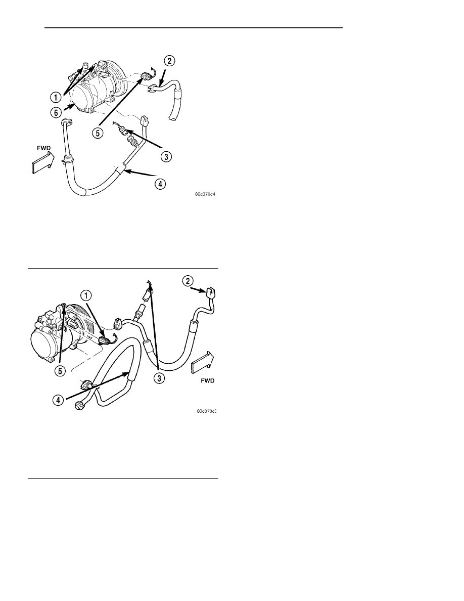
Fig. 7 A/C PRESSURE TRANSDUCER AND

DISCHARGE LINE - 3.2L/3.5L

1 - SERVICE PORTS
2 - SUCTION LINE
3 - A/C PRESSURE TRANSDUCER AND CONNECTOR
4 - DISCHARGE LINE
5 - A/C COMPRESSOR CLUTCH ELECTRICAL CONNECTOR
6 - A/C COMPRESSOR

Fig. 8 A/C PRESSURE TRANSDUCER AND

DISCHARGE LINE - 2.7L

1 - A/C COMPRESSOR CLUTCH ELECTRICAL CONNECTOR
2 - DISCHARGE LINE
3 - A/C PRESSURE TRANSDUCER AND CONNECTOR
4 - SUCTION LINE
5 - A/C COMPRESSOR

LH

PLUMBING

24 - 35

A/C DISCHARGE LINE (Continued)

(4) Disconnect the liquid line fastener at the

receiver/drier (the short receiver/drier to evaporator
line may be removed at this step).

(5) Disconnect receiver/drier bracket fastener and

separate the bracket from the strut panel (there are
two hidden plastic fasteners to pry out).

(6) Disconnect the liquid line fastener at the con-

denser (M10 Hex).

NOTE: The radiator upper crossmember must be
removed to access the liquid line fastener. Refer to
Body for the procedures.

(7) Remove the liquid line mounting clamp fas-

tener located near the service port (Fig. 9).

(8) Disconnect the liquid line fastener at the

receiver/drier. Remove the liquid line from the vehi-
cle. Cap off all fittings to prevent moisture from
entering the refrigerant system.

INSTALLATION

WARNING: REVIEW THE WARNINGS IN THE FRONT
OF THIS SECTION BEFORE PERFORMING THE
FOLLOWING OPERATION. (Refer to 24 - HEATING &
AIR CONDITIONING/PLUMBING - WARNING)

Any kinks or sharp bends in the refrigerant plumb-

ing will reduce the capacity of the entire air condi-
tioning system. Kinks and sharp bends reduce the

flow of refrigerant in the system. A good rule for the
flexible hose refrigerant lines is to keep the radius of
all bends at least ten times the diameter of the hose.
In addition, the flexible hose refrigerant lines should
be routed so they are at least 80 millimeters (3
inches) from the exhaust manifold.

High pressures are produced in the refrigerant sys-

tem when the air conditioning compressor is operat-
ing. Extreme care must be exercised to make sure
that each of the refrigerant system connections is
pressure-tight and leak free. It is a good practice to
inspect all flexible hose refrigerant lines at least once
a year to make sure they are in good condition and
properly routed.

(1) Place the liquid line in the vehicle.
(2) Install the liquid line fitting to the receiver/

drier. Tighten the fastener to 13.6 N·m (10 ft. lbs.).

(3) Install the liquid line mounting clamp fastener

located near the service port. Tighten the fastener to
6.8 N·m (5 ft. lbs.).

(4) Install the liquid line fastener at the condenser.

Tighten the fastener to 23 N·m (17 ft. lbs.).

(5) Connect the receiver/drier bracket fastener and

the bracket to the strut panel.

(6) Install the the short receiver/drier to evapora-

tor line. Tighten the fastener to 13.6 N·m (10 ft. lbs.).

(7) Connect the a/c line to the expansion valve.

Tighten the retaining bolt to 8 N·m (6 ft. lbs.).

(8) Install the engine air inlet tube and the air dis-

tribution duct on vehicles equipped with 3.2/3.5 L
engines(Refer to 9 - ENGINE/AIR INTAKE SYSTEM/
AIR CLEANER ELEMENT - INSTALLATION).

(9) Evacuate the refrigerant system. (Refer to 24 -

HEATING & AIR CONDITIONING/PLUMBING -
STANDARD PROCEDURE - REFRIGERANT SYS-
TEM EVACUATE)

(10) Charge the refrigerant system. (Refer to 24 -

HEATING & AIR CONDITIONING/PLUMBING -
STANDARD PROCEDURE - REFRIGERANT SYS-
TEM CHARGE)

SUCTION LINE

REMOVAL

WARNING: REVIEW THE WARNINGS IN THE FRONT
OF THIS SECTION BEFORE PERFORMING THE
FOLLOWING OPERATION. (Refer to 24 - HEATING &
AIR CONDITIONING/PLUMBING - WARNING)

(1) Recover the refrigerant from the system. (Refer

to 24 - HEATING & AIR CONDITIONING/PLUMB-
ING - STANDARD PROCEDURE - REFRIGERANT
RECOVERY)

(2) Remove one M13 nut holding the suction line

to the expansion valve (Fig. 10) and (Fig. 11).

Fig. 9 LIQUID LINES

1 - LIQUID LINE
2 - EXPANSION VALVE
3 - LIQUID LINE
4 - MOUNTING CLAMP
5 - SERVICE PORT
6 - RECEIVER/DRIER AND BRACKET

24 - 36

PLUMBING

LH

LIQUID LINE (Continued)

CAUTION: Cap all lines that are not being replaced
and cap the expansion valve tubes.

(3) Remove the engine air inlet tube and air distri-

bution duct for access to the compressor lines.

(4) Remove the bolt holding the line at the com-

pressor using a 6mm allen wrench (3.2/3.5L), or M10
Hex (2.7L) (Fig. 12) and (Fig. 13).

Fig. 10 A/C REFRIGERANT LINES AND EXPANSION

VALVE 3.2/3.5 L

1 - A/C COMPRESSOR
2 - EXPANSION VALVE
3 - SUCTION LINE
4 - RECEIVER/DRIER
5 - DISCHARGE LINE
6 - A/C PRESSURE TRANSDUCER
7 - LIQUID LINE

Fig. 11 A/C REFRIGERANT LINES AND EXPANSION

VALVE 2.7L

1 - A/C PRESSURE TRANSDUCER
2 - SERVICE PORT
3 - EXPANSION VALVE
4 - RECEIVER/DRIER
5 - A/C COMPRESSOR
6 - LIQUID LINE
7 - DISCHARGE LINE
8 - SUCTION LINES

Fig. 12 SUCTION LINE 3.2L/3.5L

1 - SUCTION LINE
2 - EXPANSION VALVE
3 - LIQUID LINE

Fig. 13 SUCTION LINE 2.7L

1 - SERVICE PORT
2 - SUCTION LINE
3 - EXPANSION VALVE
4 - LIQUID LINE

LH

PLUMBING

24 - 37

SUCTION LINE (Continued)

(5) Remove the line by pulling the rear end of the

line up out of the vehicle with the compressor end
following through the tie-rod area.

INSTALLATION

WARNING: REVIEW THE WARNINGS IN THE FRONT
OF THIS SECTION BEFORE PERFORMING THE
FOLLOWING OPERATION. (Refer to 24 - HEATING &
AIR CONDITIONING/PLUMBING - WARNING)

Any kinks or sharp bends in the refrigerant plumb-

ing will reduce the capacity of the entire air condi-
tioning system. Kinks and sharp bends reduce the
flow of refrigerant in the system. A good rule for the
flexible hose refrigerant lines is to keep the radius of
all bends at least ten times the diameter of the hose.
In addition, the flexible hose refrigerant lines should
be routed so they are at least 80 millimeters (3
inches) from the exhaust manifold.

High pressures are produced in the refrigerant sys-

tem when the air conditioning compressor is operat-
ing. Extreme care must be exercised to make sure
that each of the refrigerant system connections is
pressure-tight and leak free. It is a good practice to
inspect all flexible hose refrigerant lines at least once
a year to make sure they are in good condition and
properly routed.

(1) Position the suction line in the vehicle.
(2) Install the suction line fitting to the manifold

on the compressor. Tighten the mounting bolt to 23
N·m (17 ft. lbs.). On a 2.7L, tighten the mid-line
retaining nut and frame rail screw to 7 N·m (5 ft.
lbs.).

(3) Install the engine air inlet tube and air distri-

bution duct(Refer to 9 - ENGINE/AIR INTAKE SYS-
TEM/AIR CLEANER ELEMENT - INSTALLATION).

(4) Connect the suction line to the expansion

valve. Tighten the retaining nut to 8 N·m (6 ft. lbs.).

(5) Evacuate the refrigerant system. (Refer to 24 -

HEATING & AIR CONDITIONING/PLUMBING -
STANDARD PROCEDURE - REFRIGERANT SYS-
TEM EVACUATE)

(6) Charge the refrigerant system. (Refer to 24 -

HEATING & AIR CONDITIONING/PLUMBING -
STANDARD PROCEDURE - REFRIGERANT SYS-
TEM CHARGE)

A/C EVAPORATOR

REMOVAL

WARNING: ON VEHICLES EQUIPPED WITH AIR-
BAGS, DISABLE THE AIRBAG SYSTEM BEFORE
ATTEMPTING ANY STEERING WHEEL, STEERING
COLUMN, OR INSTRUMENT PANEL COMPONENT

DIAGNOSIS OR SERVICE. DISCONNECT AND ISO-
LATE THE BATTERY NEGATIVE (GROUND) CABLE,
THEN WAIT TWO MINUTES FOR THE AIRBAG SYS-
TEM CAPACITOR TO DISCHARGE BEFORE PER-
FORMING FURTHER DIAGNOSIS OR SERVICE. THIS
IS THE ONLY SURE WAY TO DISABLE THE AIRBAG
SYSTEM. FAILURE TO TAKE THE PROPER PRE-
CAUTIONS COULD RESULT IN AN ACCIDENTAL
AIRBAG DEPLOYMENT AND POSSIBLE PERSONAL
INJURY.

WARNING: REVIEW THE WARNINGS IN THE FRONT
OF THIS SECTION BEFORE PERFORMING THE
FOLLOWING OPERATION. (Refer to 24 - HEATING &
AIR CONDITIONING/PLUMBING - WARNING)

The HVAC housing must be removed from the

vehicle when replacing the evaporator.

(1) Open the hood and disconnect the negative bat-

tery cable remote terminal from the remote battery
post.

(2) Remove the HVAC housing from vehicle. (Refer

to 24 - HEATING & AIR CONDITIONING/DISTRI-
BUTION/HVAC HOUSING - REMOVAL)

(3) Remove the recirculation door actuator(Refer to

24 - HEATING & AIR CONDITIONING/CONTROLS/
RECIRCULATION DOOR ACTUATOR - REMOVAL).

(4) Remove the recirculation door and housing.
(5) Remove the upper HVAC housing retaining

screws(Refer to 24 - HEATING & AIR CONDITION-
ING/DISTRIBUTION/HVAC

HOUSING

-

DISAS-

SEMBLY).

(6) At the center of the HVAC housing, locate the

evaporator probe access plate. Using a flat blade pry
tool, pull back on the locking tab. Twist the access
plate counter clockwise one-quarter turn, and push
the plate inside the HVAC housing.

(7) Remove the upper half of the HVAC housing.
(8) Lift the evaporator out of the lower housing.

INSTALLATION

WARNING: REVIEW THE WARNINGS IN THE FRONT
OF THIS SECTION BEFORE PERFORMING THE
FOLLOWING OPERATION. (Refer to 24 - HEATING &
AIR CONDITIONING/PLUMBING - WARNING)

Any kinks or sharp bends in the refrigerant plumb-

ing will reduce the capacity of the entire air condi-
tioning system. Kinks and sharp bends reduce the
flow of refrigerant in the system. A good rule for the
flexible hose refrigerant lines is to keep the radius of
all bends at least ten times the diameter of the hose.
In addition, the flexible hose refrigerant lines should
be routed so they are at least 80 millimeters (3
inches) from the exhaust manifold.

24 - 38

PLUMBING

LH

SUCTION LINE (Continued)


Content   ..  399  400  401  402   ..