Chrysler 300M, Dodge Interpid. Manual - part 400


  Index      Chrysler     Chrysler 300M / Concorde / Interpid / LHS, Dodge Interpid - service repair manual 2000-2004 year


Search            


Content   ..  398  399  400  401   ..


Chrysler 300M, Dodge Interpid. Manual - part 400


STANDARD PROCEDURE - REFRIGERANT
SYSTEM CHARGE

WARNING: REVIEW THE WARNINGS IN THE FRONT
OF THIS SECTION BEFORE PERFORMING THE
FOLLOWING OPERATION. (Refer to 24 - HEATING &
AIR CONDITIONING/PLUMBING - WARNING)

After the refrigerant system has been tested for

leaks and evacuated, a refrigerant charge can be
injected into the system. (Refer to 24 - HEATING &
AIR CONDITIONING/PLUMBING - SPECIFICA-
TIONS - CHARGE CAPACITY)

A R-134a refrigerant recovery/recycling/charging

station that meets SAE Standard J2210 must be
used to charge the refrigerant system with R-134a
refrigerant. Refer to the operating instructions sup-
plied by the equipment manufacturer for proper care
and use of this equipment.

SPECIFICATIONS

CHARGE CAPACITY

NOTE: Always refer to the vehicle’s underhood
HVAC Specification label for the correct charge
specifications.

A/C COMPRESSOR

DESCRIPTION

The air conditioning system uses a Nippondenso

10PA17 ten cylinder, double-acting swash plate-type
compressor on all models. This compressor has a
fixed displacement of 170 cubic centimeters (10.374
cubic inches), and has both the suction and discharge
ports located on the cylinder head. A label identifying
the use of R-134a refrigerant is located on the com-
pressor. This compressor uses an aluminum swash
plate, teflon coated pistons and aluminum cylinder
walls. One-way check valves are used to regulate
refrigerant flow through the compressor.

CAUTION: A 10PA17 R-12 compressor looks identi-
cal to a 10PA17 R134a and will bolt up to this vehi-
cle.

It

is

extremely

important

that

a

R-134a

compressor is identified prior to using compressor
in question. Check tag located on compressor for
model number.

OPERATION

The compressor is driven by the engine through an

electric clutch, drive pulley and belt arrangement.
The compressor is lubricated by refrigerant oil that is
circulated throughout the refrigerant system with the
refrigerant.

The compressor draws in low-pressure refrigerant

vapor from the evaporator through its suction port. It
then compresses the refrigerant into a high-pressure,
high-temperature refrigerant vapor, which is then
pumped to the condenser through the compressor dis-
charge port.

The compressor cannot be repaired. If faulty or

damaged, the entire compressor assembly must be
replaced. The compressor clutch, pulley and clutch
coil are available for service.

DIAGNOSIS AND TESTING - COMPRESSOR
NOISE

Excessive noise that occurs when the air-condition-

ing is being used may be caused by:

• Loose Bolts

• Mounting Brackets

• Loose Compressor Clutch

• Excessive High Refrigerant Operating Pressure
Verify the following before compressor repair is

performed:

(1) Compressor drive belt condition
(2) Proper refrigerant charge
(3) Thermal expansion valve (TXV) operating cor-

rectly

(4) Head pressure is normal

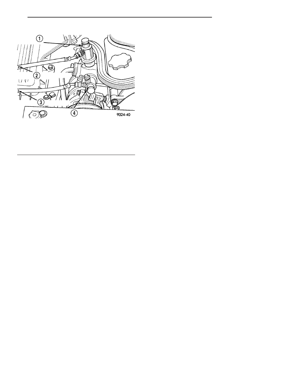
Fig. 2 GAUGE SET OR REFRIGERANT RECOVERY

MACHINE HOOKUP (3.2 / 3.5L)

1 - HIGH SIDE CONNECTOR
2 - TO MANIFOLD GAUGE SET
3 - TO MANIFOLD GAUGE SET
4 - LOW SIDE CONNECTOR

LH

PLUMBING

24 - 31

PLUMBING (Continued)

REMOVAL

The A/C compressor may be unbolted and reposi-

tioned without discharging the refrigerant system.
Discharging is not necessary if removing the com-
pressor clutch/coil assembly, engine, cylinder head, or
alternator.

WARNING: REVIEW THE WARNINGS IN THE FRONT
OF THIS SECTION BEFORE PERFORMING THE
FOLLOWING OPERATION. (Refer to 24 - HEATING &
AIR CONDITIONING/PLUMBING - WARNING)

(1) Disconnect the negative battery cable remote

terminal from the remote battery post.

(2) Loosen and remove the drive belts(Refer to 7 -

COOLING/ACCESSORY

DRIVE/DRIVE

BELTS

-

REMOVAL) or (Refer to 7 - COOLING/ACCESSORY
DRIVE/DRIVE BELTS - REMOVAL).

(3) Disconnect the compressor clutch wire lead.
(4) Recover the refrigerant from the system. (Refer

to 24 - HEATING & AIR CONDITIONING/PLUMB-
ING - STANDARD PROCEDURE - REFRIGERANT
RECOVERY)

(5) Remove the refrigerant lines from the compres-

sor.

(6) If system is going to be left open, plug or cap

the open lines.

(7) Remove compressor attaching bolts (Fig. 3) and

(Fig. 4).

(8) Remove the compressor.

INSTALLATION

WARNING: REVIEW THE WARNINGS IN THE FRONT
OF THIS SECTION BEFORE PERFORMING THE
FOLLOWING OPERATION. (Refer to 24 - HEATING &
AIR CONDITIONING/PLUMBING - WARNING)

Any kinks or sharp bends in the refrigerant plumb-

ing will reduce the capacity of the entire air condi-
tioning system. Kinks and sharp bends reduce the
flow of refrigerant in the system. A good rule for the
flexible hose refrigerant lines is to keep the radius of
all bends at least ten times the diameter of the hose.
In addition, the flexible hose refrigerant lines should
be routed so they are at least 80 millimeters (3
inches) from the exhaust manifold.

High pressures are produced in the refrigerant sys-

tem when the air conditioning compressor is operat-
ing. Extreme care must be exercised to make sure
that each of the refrigerant system connections is
pressure-tight and leak free. It is a good practice to
inspect all flexible hose refrigerant lines at least once
a year to make sure they are in good condition and
properly routed.

NOTE:

If

a

replacement

compressor

is

being

installed, be certain to check the refrigerant oil
level. (Refer to 24 - HEATING & AIR CONDITIONING/
PLUMBING/REFRIGERANT OIL - STANDARD PRO-
CEDURE) Use only refrigerant oil of the type
recommended for the compressor in the vehicle.
(Refer to 24 - HEATING & AIR CONDITIONING/
PLUMBING/REFRIGERANT OIL - DESCRIPTION)

Fig. 3 COMPRESSOR MOUNTING - 2.7L

1 - HIGH PRESSURE RELIEF VALVE
2 - A/C COMPRESSOR
3 - MOUNTING BOLTS
4 - PUSH PIN
5 - ENGINE OIL COOLER BRACKET

Fig. 4 COMPRESSOR MOUNTING - 3.2L/3.5L

1 - SERVICE PORTS
2 - MOUNTING BOLTS
3 - A/C COMPRESSOR
4 - HIGH PRESSURE RELIEF VALVE

24 - 32

PLUMBING

LH

A/C COMPRESSOR (Continued)

(1) Position the a/c compressor in the vehicle and

install the attaching bolts. Torque the a/c compressor
mounting bolts to 28 N·m (21 ft. lbs.)

(2) Remove the plug or cap from the opened refrig-

erant line fittings. Install new O-rings and lubricate
with refrigerant oil. Install the suction line and dis-
charge line fittings to the manifold on the a/c com-
pressor. Tighten the fasteners to 23 N·m (17 ft. lbs.).

(3) Install the drive belts(Refer to 7 - COOLING/

ACCESSORY DRIVE/DRIVE BELTS - INSTALLA-
TION) or (Refer to 7 - COOLING/ACCESSORY
DRIVE/DRIVE BELTS - INSTALLATION).

(4) Connect the a/c compressor clutch coil wire

lead.

(5) Connect the negative battery cable remote ter-

minal from the remote battery post.

(6) Evacuate the refrigerant system. (Refer to 24 -

HEATING & AIR CONDITIONING/PLUMBING -
STANDARD PROCEDURE - REFRIGERANT SYS-
TEM EVACUATE)

(7) Charge the refrigerant system. (Refer to 24 -

HEATING & AIR CONDITIONING/PLUMBING -
STANDARD PROCEDURE - REFRIGERANT SYS-
TEM CHARGE)

A/C CONDENSER

REMOVAL

WARNING: REVIEW THE WARNINGS IN THE FRONT
OF THIS SECTION BEFORE PERFORMING THE
FOLLOWING OPERATION. (Refer to 24 - HEATING &
AIR CONDITIONING/PLUMBING - WARNING)

The condenser is located between the radiator and

the front bumper. The condenser can be serviced
without having to drain the cooling system or remove
the radiator.

(1) Open the hood and disconnect the negative bat-

tery cable remote terminal from the remote battery
post.

(2) Recover the refrigerant from the system. (Refer

to 24 - HEATING & AIR CONDITIONING/PLUMB-
ING - STANDARD PROCEDURE - REFRIGERANT
RECOVERY)

(3) Remove the retainers for the upper radiator

core support and place aside(Refer to 7 - COOLING/
ENGINE/RADIATOR - REMOVAL).

(4) Undo the auxiliary transmission cooler hose fit-

tings (Do not open the fittings at the Cooler) (Fig. 5)
or (Fig. 6).

(5) Remove the screw and retainer bracket for the

auxiliary transmission cooler lines.

(6) Remove the discharge line fastener at con-

denser.

(7) Remove the liquid line fastener at condenser.

(8) Remove two screws retaining the condenser to

the radiator.

(9) Separate the condenser from the radiator.

Fig. 5 A/C CONDENSER TO RADIATOR - 2.7L

WITHOUT AUTO STICK

1 - TRANSMISSION OIL COOLER LINE MOUNTING BRACKET
2 - A/C CONDENSER TO RADIATOR MOUNTING SCREWS

Fig. 6 A/C CONDENSER TO RADIATOR - 3.2/3.5L &

2.7L W/AUTO STICK

1 - TRANS COOLER LINE BRACKET SCREW
2 - SCREW - CONDENSER TO RADIATOR
3 - TRANS COOLER
4 - SCREW - CONDENSER TO RADIATOR

LH

PLUMBING

24 - 33

A/C COMPRESSOR (Continued)

(10) Remove the condenser (with auxiliary trans-

mission cooler attached) from the vehicle.

(11) Cut the auxiliary transmission cooler retain-

ing straps.

NOTE: The new condenser will include new retain-
ing straps for the auxiliary transmission cooler
attachment to new condenser assembly.

CAUTION: Avoid bending or breaking condenser
inlet tube when lifting radiator/condenser assembly
from the vehicle.

INSTALLATION

WARNING: REVIEW THE WARNINGS IN THE FRONT
OF THIS SECTION BEFORE PERFORMING THE
FOLLOWING OPERATION. (Refer to 24 - HEATING &
AIR CONDITIONING/PLUMBING - WARNING)

Any kinks or sharp bends in the refrigerant plumb-

ing will reduce the capacity of the entire air condi-
tioning system. Kinks and sharp bends reduce the
flow of refrigerant in the system. A good rule for the
flexible hose refrigerant lines is to keep the radius of
all bends at least ten times the diameter of the hose.
In addition, the flexible hose refrigerant lines should
be routed so they are at least 80 millimeters (3
inches) from the exhaust manifold (Whenever possi-
ble).

High pressures are produced in the refrigerant sys-

tem when the air conditioning compressor is operat-
ing. Extreme care must be exercised to make sure
that each of the refrigerant system connections is
pressure-tight and leak free. It is a good practice to
inspect all flexible hose refrigerant lines at least once
a year to make sure they are in good condition and
properly routed.

(1) Install the auxiliary transmission cooler in the

same position on the condenser with new retaining
straps.

(2) Install the condenser in the vehicle.
(3) Install the two screws retaining the condenser

to the radiator. Tighten the screws to 10.5 N·m (95
in. lbs.).

NOTE: Always install NEW O-rings and lubricate
with refrigerant oil.

(4) Connect the liquid line to the condenser inlet.

Tighten the retaining nut to 23 N·m (17 ft. lbs.).

(5) Connect the discharge line to the condenser

outlet. Tighten the retaining nut to 23 N·m (17 ft.
lbs.).

(6) Install the retainer bracket and screw for the

auxiliary transmission cooler lines.

(7) Connect the auxiliary transmission cooler hose

fittings.

(8) Install the upper radiator core support(Refer to

7 - COOLING/ENGINE/RADIATOR - INSTALLA-
TION).

(9) Connect the negative battery cable remote ter-

minal to the remote battery post.

(10) Evacuate the refrigerant system. (Refer to 24

- HEATING & AIR CONDITIONING/PLUMBING -
STANDARD PROCEDURE - REFRIGERANT SYS-
TEM EVACUATE)

(11) Charge the refrigerant system. (Refer to 24 -

HEATING & AIR CONDITIONING/PLUMBING -
STANDARD PROCEDURE - REFRIGERANT SYS-
TEM CHARGE)

A/C DISCHARGE LINE

REMOVAL

WARNING: REVIEW THE WARNINGS IN THE FRONT
OF THIS SECTION BEFORE PERFORMING THE
FOLLOWING OPERATION. (Refer to 24 - HEATING &
AIR CONDITIONING/PLUMBING - WARNING)

(1) Open the hood and disconnect the negative bat-

tery cable remote terminal from the remote battery
post.

(2) Recover the refrigerant from the system. (Refer

to 24 - HEATING & AIR CONDITIONING/PLUMB-
ING - STANDARD PROCEDURE -REFRIGERANT
RECOVERY)

(3) Disconnect the a/c pressure transducer wire

harness (Fig. 7) and (Fig. 8).

(4) Remove the a/c pressure transducer. (Refer to

24 - HEATING & AIR CONDITIONING/CONTROLS/
A/C PRESSURE TRANSDUCER - REMOVAL)

(5) Disconnect the discharge line at the compressor

using an M10 Hex wrench for 2.7L, and a 6 mm
allen wrench for 3.2/3.5L.

CAUTION: Cap all lines that are not being replaced
and cap the expansion valve tubes.

(6) Disconnect the discharge line at the A/C con-

denser using an M10 Hex wrench.

INSTALLATION

WARNING: REVIEW THE WARNINGS IN THE FRONT
OF THIS SECTION BEFORE PERFORMING THE
FOLLOWING OPERATION. (Refer to 24 - HEATING &
AIR CONDITIONING/PLUMBING - WARNING)

24 - 34

PLUMBING

LH

A/C CONDENSER (Continued)


Content   ..  398  399  400  401   ..