Chrysler 300M, Dodge Interpid. Manual - part 318


  Index      Chrysler     Chrysler 300M / Concorde / Interpid / LHS, Dodge Interpid - service repair manual 2000-2004 year


Search            


Content   ..  316  317  318  319   ..


Chrysler 300M, Dodge Interpid. Manual - part 318


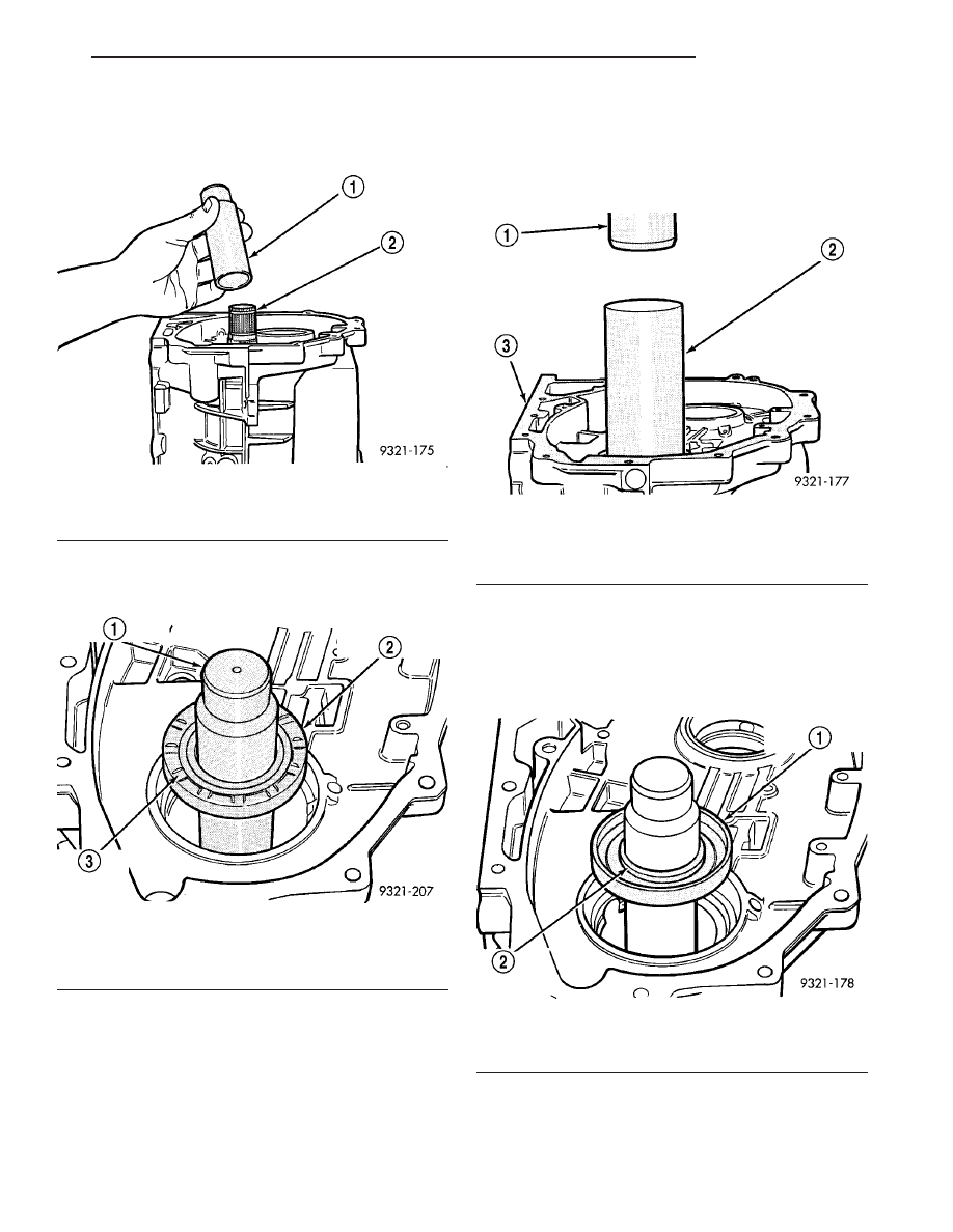
(35) Install transfer shaft seal protector (special

tool 6592) (Fig. 217). Apply thin film of gear oil to
protector.

(36) Apply a small amount of lube to seal lips and

install front transfer shaft seal. The serrated edges
must face toward the rear of the transaxle (Fig. 218).

(37) Install seal with special tool 6567A (Fig. 219).

Use a press to install seal. The installation tool will
set the seal depth. Do not use a hammer to install
seal. The seal may be damaged if installed with a
hammer.

(38) Install rear transfer shaft seal. The seal must

be installed so that the spring side of the seal faces
the installation tool (Fig. 220). Use the same special
tool (6567A) to install the seal. The installation tool
will set the seal depth. Use a press to install this
seal. Do not use a hammer.

Fig. 217 Seal Protector Installation

1 - SEAL PROTECTOR
2 - TRANSFER SHAFT

Fig. 218 Correct Seal Orientation

1 - SEAL PROTECTOR
2 - FRONT TRANSFER SHAFT SEAL
3 - SERRATED SIDE REARWARD

Fig. 219 Seal Installation

1 - ARBOR PRESS
2 - SEAL INSTALLER (6567A)
3 - TRANSAXLE CASE

Fig. 220 Correct Seal Orientation

1 - REAR TRANSFER SHAFT SEAL
2 - SPRING SIDE OUTWARD

LH

TRANSAXLE

21 - 91

FINAL DRIVE (Continued)

(39) Install rear transfer shaft cup into case (Fig.

221).

CAUTION: Properly seated cups are essential in
correctly setting bearing preload.

(40) Use special tool 6560 to press cup into case

(Fig. 222).

(41) Install Transfer shaft preload shim (Fig. 223).

Use the original shim that was taken out of trans-
axle if possible. If original shim is not available, use

the thickest shim as a starting point. Refer to Trans-
fer Shaft Rear Shim Chart for available sizes.

(42) Install rear transfer shaft cone. Press cone on

transfer shaft using Tool 6560.

(43) Remove transfer shaft support fixture (special

tool 6595).

CAUTION: Always use a new transfer shaft nut. Do
not reuse old transfer shaft nut.

Fig. 221 Rear Transfer Bearing Cup

1 - REAR TRANSFER BEARING CUP
2 - TRANSFER SHAFT

Fig. 222 Rear Transfer Shaft Cup Installation

1 - ARBOR PRESS
2 - SPECIAL TOOL 6560

Fig. 223 Transfer Preload Shim Installation

1 - TRANSFER SHAFT PRELOAD SHIM
2 - TRANSFER SHAFT

Transfer Shaft Rear Shim Chart

21 - 92

TRANSAXLE

LH

FINAL DRIVE (Continued)

(44) Install a new transfer shaft nut (Fig. 224).

Tighten nut to 271 N·m (200 ft. lbs.). Use special
tools 6497 holder and 6498 shaft socket to tighten
nut.

CAUTION: Failure to set the transfer shaft turning
torque correctly may cause transfer shaft bearings or
seals to fail. Be sure transfer shaft does not have end
play. If end play exists, install a thinner preload shim.

(45) Check the turning torque of the transfer shaft

using a torque wrench (Fig. 225). The turning torque
should be 0.5 to 1.3 N·m (5 to 12 in. lbs.). If the turn-
ing torque is too high, install a thicker transfer shaft
preload shim. If the turning torque is too low, install
a thinner transfer shaft preload shim.

CAUTION: A press and special tool 6589 must be
used when staking the transfer shaft nut. Do not
use a hammer and the special tool to stake nut. If a
hammer is used; seal, bearing, and/or tool damage
may result. Also the stake will not be seated against
the shaft correctly. This will allow the nut to loosen.

(46) After the correct turning torque is obtained,

use special tool 6589 to stake the new transfer shaft
nut (Fig. 226) (Fig. 227). Be sure that the tool arms
line up with slots in the transfer shaft. Use a press
with the special tool to make the stakes in the nut.

Fig. 224 Transfer Shaft Nut Installation

1 - TORQUE WRENCH
2 - HOLDER (6497)
3 - SHAFT SOCKET (6498)

Fig. 225 Checking Turning Torque

1 - SOCKET (6498)
2 - TRANSFER SHAFT NUT
3 - IN. LBS. TORQUE WRENCH

Fig. 226 Staking New Nuts

1 - ARBOR PRESS
2 - STAKING TOOL (6589)

Fig. 227 Correctly Staked Nut

1 - BOTTOMED IN SLOT
2 - CORRECTLY STAKED NUT

LH

TRANSAXLE

21 - 93

FINAL DRIVE (Continued)

CAUTION: Failure to stake the transfer shaft nut
correctly may allow the nut to loosen during trans-
axle operation. This will cause transaxle failure.

(47) At this point the transfer shaft, new oil seals,

pinion depth and transfer shaft preload have been
set. The following steps will set the backlash between
the transfer shaft and the ring gear.

(48) Install vent baffle. Apply sealer as shown in

(Fig. 228).

(49) Install new inner adjuster O-ring. Lube inner

adjuster threads and O-ring. Then install inner
adjuster flush with differential side of case.

(50) Install differential assembly (with ring gear

attached) into transaxle case (Fig. 229).

(51) Transfer shaft to ring gear backlash should be

0.006

9 to 0.0099 thousands of an inch. To get the

backlash close enough to measure, perform the fol-
lowing steps. Hold the transfer shaft with one hand
and rock the ring gear back and forth (Fig. 230). You
should feel some backlash between the gears. If no
backlash is felt use special tool 6502B to turn the
inner adjuster so that it raises the differential
assembly. This will increase backlash. If there is to
much backlash, use special tool 6502B to turn the
inner adjuster so that it lowers the differential
assembly. This will decrease backlash. Recheck the
backlash after each adjustment.

Fig. 228 Vent Baffle Installation

1 - NO SEALER ON THIS EDGE
2 - APPLY SEALER
3 - VENT BAFFLE

Fig. 229 Differential Assembly Installation

1 - DIFFERENTIAL ASSEMBLY

Fig. 230 Rocking Ring Gear Back and Forth

1 - DIFFERENTIAL ASSEMBLY

21 - 94

TRANSAXLE

LH

FINAL DRIVE (Continued)


Content   ..  316  317  318  319   ..