Chrysler 300M, Dodge Interpid. Manual - part 290


  Index      Chrysler     Chrysler 300M / Concorde / Interpid / LHS, Dodge Interpid - service repair manual 2000-2004 year


Search            


Content   ..  288  289  290  291   ..


Chrysler 300M, Dodge Interpid. Manual - part 290


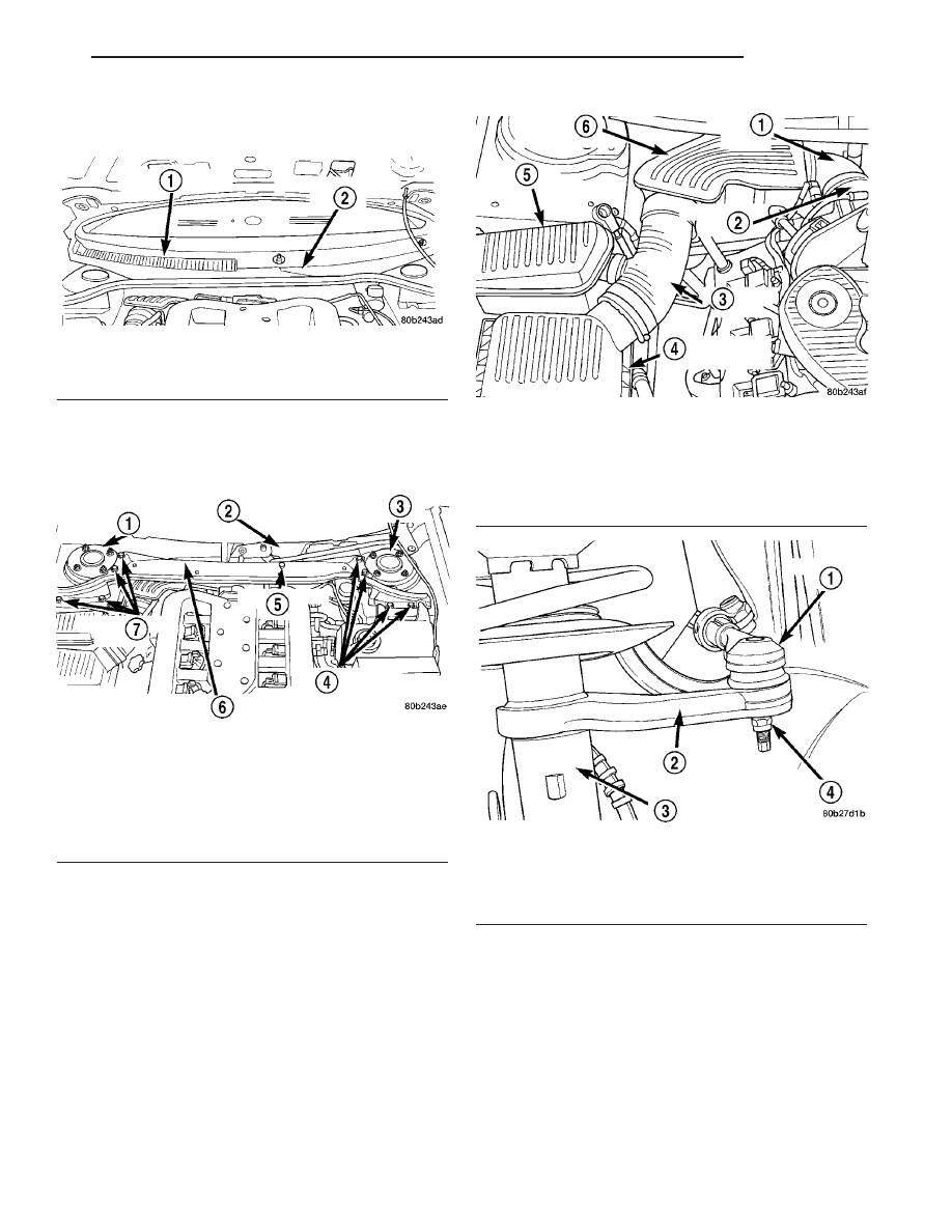
(4) Remove the wiper module cover and cowl cover

from the vehicle (Fig. 52).

(5) Remove the eight bolts attaching the cowl rein-

forcement to the strut towers and the one bolt
attaching the wiper module to the reinforcement
(Fig. 53). Remove the reinforcement from the vehicle.

(6) Remove the in-line resonator and inlet hose

from the throttle body and air let hose coming from
the lid of the air cleaner housing (Fig. 54).

(7) Raise the vehicle on a frame contact hoist until

the front tires of the vehicle are just off the floor. See
Hoisting in Lubrication And Maintenance.

(8) Remove front wheel and tire assembly from

side requiring repair (both sides are recommended).

(9) Remove the nut attaching the outer tie rod end

to the steering arm on the strut (Fig. 55).

Fig. 52 Wiper Module And Cowl Cover

1 - COWL COVER
2 - WIPER MODULE COVER

Fig. 53 Reinforcement Attachment To Vehicle

1 - RIGHT STRUT TOWER
2 - WIPER MODULE
3 - LEFT STRUT TOWER
4 - ATTACHING BOLTS
5 - ATTACHING BOLT
6 - REINFORCEMENT
7 - ATTACHING BOLTS

Fig. 54 In-Line Resonator And Air Inlet Hose

1 - AIR INLET HOSE
2 - THROTTLE BODY
3 - AIR INLET HOSE
4 - AIR CLEANER HOUSING LID
5 - RESONATOR
6 - IN-LINE RESONATOR

Fig. 55 Tie Rod End Attachment To Strut

1 - TIE ROD END
2 - STEERING ARM
3 - STRUT
4 - NUT

LH

GEAR

19 - 53

BUSHING - INNER TIE ROD (Continued)

(10) Remove the tie rod end from the steering arm

of the strut using Puller, Special Tool C-3894–A (Fig.
56).

(11) Turn the steering wheel all the way to the

full-right position.

(12) Bend back the retaining tabs on the mounting

plate for the tie rod to steering gear mounting bolts
(Fig. 57).

(13) Remove the bolt fastening the inner tie rod to

the steering gear (Fig. 58). Be careful not to loose the
washer behind the tie rod.

(14) Loosen the bolt fastening the opposite inner

tie rod to the gear, but do not fully remove it.

(15) Rotate the loose end of the mounting plate out

of the way.

(16) Remove the tie rod assembly from the vehicle

through the wheel opening.

(17) Mount Receiver, Special tool 8438–1, in a vise

as shown (Fig. 59).

(18) Assemble Special Tool 8438 in the following

manner to remove the bushing from the inner tie
rod.

(a) Place the inner tie rod bushing end in the

Receiver as shown (Fig. 59).

(b) Place Remover/Installer, Special Tool 8438–4,

with the small end down on top of the bushing
(Fig. 59).

(c) Insert Screw, Special Tool 8438–3, though the

Remover/Installer and tie rod bushing, until it
threads into the bottom of the Receiver.

(d) Using hand tools, tighten the Screw until it

bottoms out. The bushing is now removed from the
inner tie rod.
(19) Remove the Screw, then remove the Remover/

Installer, tie rod and bushing from the Receiver.

INSTALLATION - INNER TIE ROD BUSHING

NOTE: When servicing inner tie rod bushings,
replacement of bushings on both inner tie rods is
recommended.

(1) Using Mopar

t Silicone Spray Lubricant, spray

bushing, inner tie rod end, and inside of Sizer, Spe-
cial Tool 8438–2.

Fig. 56 Removing Outer Tie Rod From Steering Arm

1 - TIE ROD END
2 - STEERING ARM
3 - STRUT
4 - C-3894A

Fig. 57 Tie Rod Attachment Bolt Retaining Tabs

1 - STEERING GEAR
2 - TIE RODS
3 - RETAINING TABS
4 - BOLTS
5 - PLATE

Fig. 58 Tie Rod To Steering Gear Attaching Bolts

1 - TIE RODS
2 - BOLTS
3 - MOUNTING PLATE
4 - WASHERS
5 - STEERING GEAR

19 - 54

GEAR

LH

BUSHING - INNER TIE ROD (Continued)

CAUTION: Do not use petroleum based rubber
bushing installation lubricant. Premature bushing
failure may occur.

NOTE: The inner tie rod bushing is symmetrical.
There is no designated top or bottom.

(2) Place NEW bushing in the bore of Sizer as

shown (Fig. 60). Slide bushing all the way into the
Sizer bore.

(3) With

the

Receiver,

Special

Tool

8438–1,

mounted in the vise as shown (Fig. 61), assemble the
Special Tool 8438 in the following manner to install
the new bushing.

(a) Place the inner tie rod end in Receiver as

shown (Fig. 61).

(b) Place the Sizer (with bushing) on top of the

tie rod bushing bore with the tapered end facing
downward.

(c) Place Remover/Installer, Special Tool 8438–4,

with the small end down on top of the bushing
(Fig. 61).

(d) Insert Screw, Special Tool 8438–3, through

the Remover/Installer, bushing (in Sizer) and tie
rod, until it threads into the bottom of the
Receiver.

(e) Using hand tools, tighten the Screw, pushing

the bushing out of Sizer, into the inner tie rod end.
Tighten the Screw until it bottoms in the tool. Do
not overtighten.

Fig. 59 Special Tool 8438 Set Up For Removal

1 - 8438-3 (SCREW)
2 - INNER TIE ROD
3 - VISE
4 - 8438-1 (RECEIVER)
5 - BUSHING
6 - 8438-4 (REMOVER/INSTALLER)

Fig. 60 Bushing Installation Into 8438-2 (Sizer)

Fig. 61 Special Tool 8438 Set Up For Installation

1 - 8438-3 (SCREW)
2 - BUSHING
3 - INNER TIE ROD
4 - VISE
5 - 8438-1 (RECEIVER)
6 - 8438-2 (SIZER)
7 - 8438-4 (REMOVER/INSTALLER)

LH

GEAR

19 - 55

BUSHING - INNER TIE ROD (Continued)

(4) Remove

the

Screw,

Remover/Installer

and

Sizer, then remove the tie rod from the Receiver.

(5) Inspect the bushing. It will appear slightly off-

center in the tie rod (Fig. 62). This is a normal con-
dition.

NOTE: Before installing the tie rod assembly back
in the vehicle, loosen the tie rod adjustment pinch
bolt and verify the adjustment sleeve is freed-up.
This will ease toe adjustment which must be set at
the end of this procedure.

(6) Install the tie rod assembly through the tie rod

hole in the wheel opening inner fender.

(7) Install the outer tie rod on the steering arm of

the strut. Install the tie rod steering arm nut (Fig.
55). Do not tighten the nut at this time.

CAUTION: Before installing tie rod on steering gear
be sure the tie rod spacer block inside the steering
gear bellows (boot) is correctly aligned with the bolt
holes in the rack of the steering gear and the steer-
ing gear bellows (Fig. 63).

(8) Align the inner tie rod with the mounting hole in

the center take off on steering gear. Rotate the mount-
ing plate into position over the tie rod. Install tie rod
attaching bolt through tie rod and washer into steering
gear. Be sure washer is installed between tie rod
and steering gear as shown (Fig. 64).

NOTE: It is recommended that the opposite inner tie
rod’s bushing be removed and replaced at this
time. Refer to Removal.

Fig. 62 Correctly Installed Bushing

1 - INNER TIE ROD
2 - BUSHING OFF-CENTER

Fig. 63 Tie Rod Spacer Block

1 - STEERING GEAR BOOT
2 - SPACER BLOCK

Fig. 64 Tie Rod Attachment

1 - RETAINING TABS
2 - BOLTS
3 - RETAINING PLATE
4 - STEERING GEAR
5 - WASHER
6 - TIE RODS
7 - WASHER

19 - 56

GEAR

LH

BUSHING - INNER TIE ROD (Continued)


Content   ..  288  289  290  291   ..