Chrysler 300M, Dodge Interpid. Manual - part 270


  Index      Chrysler     Chrysler 300M / Concorde / Interpid / LHS, Dodge Interpid - service repair manual 2000-2004 year


Search            


Content   ..  268  269  270  271   ..


Chrysler 300M, Dodge Interpid. Manual - part 270


INSTALLATION

INSTALLATION - 2.7L

(1) Lightly lubricate the fuel injector O-rings with

a couple drops of clean engine oil.

(2) Install retaining clips on fuel injectors.
(3) Push injectors into fuel injector rail until clips

are in the correct position.

(4) Position fuel rail over cylinder heads, and push

rail into place. Tighten fuel rail mounting bolts to 11
N·m (100 in. lbs.) torque.

(5) Connect the fuel supply tube quick connect fit-

ting to the fuel rail. Refer to Quick Connect Fittings
in the Fuel Delivery Section.

(6) Connect the electrical connectors to the fuel

injectors.

(7) Install intake manifold plenum. Refer to the

Engine section for information.

(8) Connect negative cable to battery.

INSTALLATION - 3.5L

(1) Lightly lubricate the fuel injector O-rings with

a couple drops of clean engine oil.

(2) Install retaining clips on fuel injectors.
(3) Push injectors into fuel injector rail until clips

are in the correct position.

(4) Position fuel rail over cylinder heads, and push

rail into place. Tighten fuel rail mounting bolts to 28
N·m (250 in. lbs.) torque.

(5) Connect the fuel supply tube quick connect fit-

ting to the fuel rail. Refer to Quick Connect Fittings
in the Fuel Delivery Section.

(6) Connect the electrical connectors to the fuel

injectors.

(7) Install intake manifold plenum. Refer to the

Engine section for information.

(8) Connect negative cable to battery.

FUEL TANK

DESCRIPTION

The fuel tank is constructed of a plastic material.

Its main functions are for fuel storage and for place-
ment of the fuel pump module. The tank is made
from High density Polyethylene (HDPE) material.If
equipped with ORVR (Onboard Refueling Vapor
Recovery) it has been added to the fuel tank to con-
trol refueling vapor emissions.

OPERATION

All models pass a full 360 degree rollover test

without fuel leakage. To accomplish this, fuel and
vapor flow controls are required for all fuel tank con-
nections.

All models are equipped with either one or two

rollover valves mounted into the top of the fuel tank
(or pump module).

An evaporation control system is connected to the

rollover valve(s)/control valve(Refer to 25 - EMIS-
SIONS

CONTROL/EVAPORATIVE

EMISSIONS/

ORVR - OPERATION) to reduce emissions of fuel
vapors into the atmosphere, when the tank is vented
due to vapor expansion in the tank. When fuel evap-
orates from the fuel tank, vapors pass through vent
hoses or tubes to a charcoal canister where they are
temporarily held. When the engine is running, the
vapors are drawn into the intake manifold. In addi-
tion, fuel vapors produced during vehicle refueling
are allowed to pass through the vent hoses/tubes to
the charcoal canister(s) for temporary storage (prior
to being drawn into the intake manifold). All models
are equipped with a self-diagnosing system using a
Natural Vacuum Leak Detection (NVLD). Refer to
the Emission Control System for additional informa-
tion.

INLET CHECK VALVE

All vehicles have an inlet check valve on the inside

of the fuel tank at the filler inlet

The valve prevents fuel from splashing back on

customer during vehicle refueling. The valve is a
non-serviceable item.

REMOVAL

(1) Release fuel pressure, Refer to Fuel System

Pressure Release Procedure.

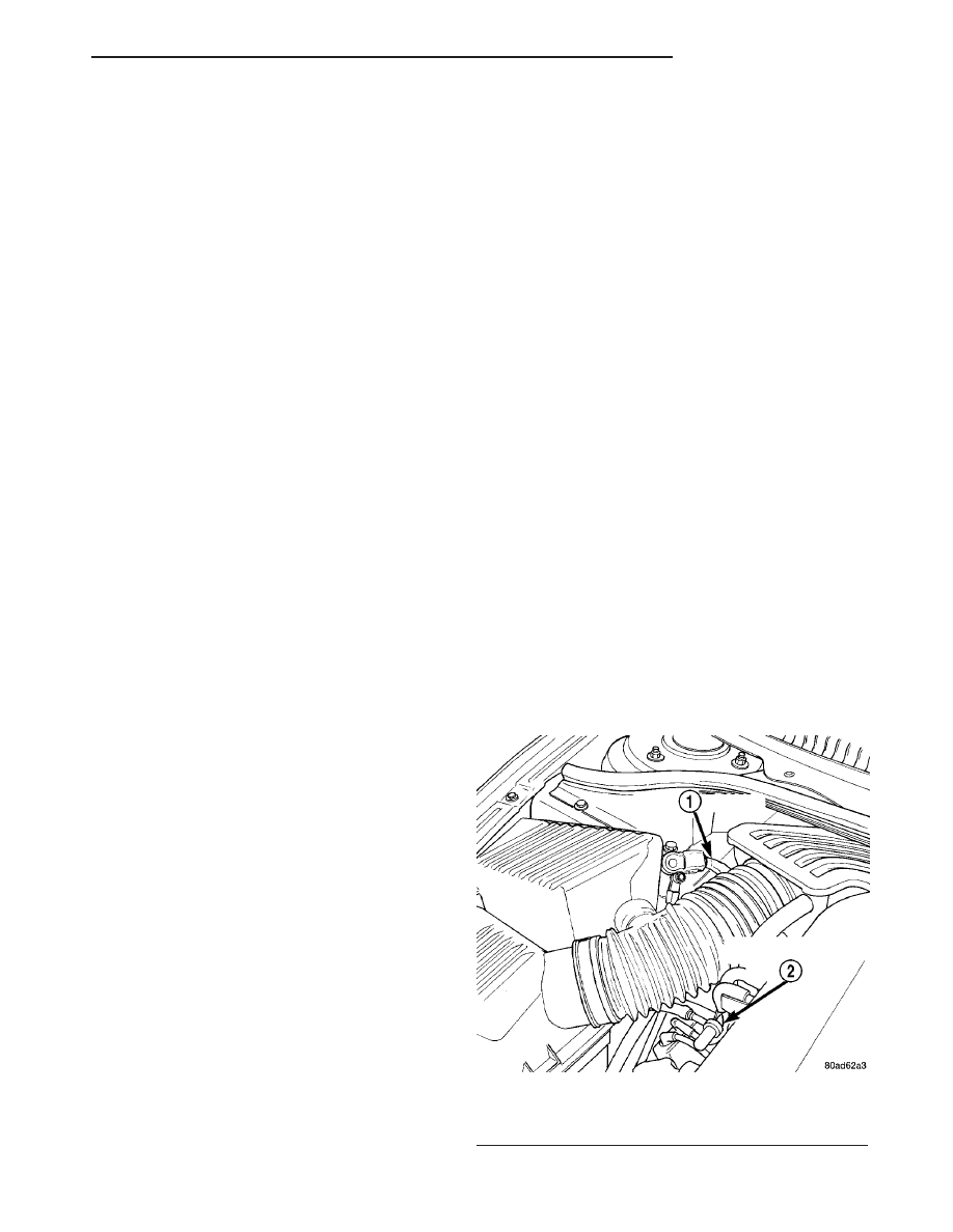
(2) Disconnect battery cable (Fig. 13).

Fig. 13 Battery Cable

1 - BATTERY CABLE
2 - SERVICE VACUUM SUPPLY TEE

LH

FUEL DELIVERY

14 - 9

FUEL RAIL (Continued)

(3) Remove rear seat, refer to the Body section for

more information.

(4) Disconnect fuel pump electrical connector (Fig. 14).

(5) Raise vehicle and support.

NOTE: To drain fuel tank it is best to have less than
1/2 a tank of fuel.

(6) To drain fuel tank, place container under fuel

filler tube at fuel tank. Loosen and remove fuel filler
tube from fuel tank (Fig. 15). Stick siphon hose into
tank at fuel filler tube connection, and drain fuel
tank.

(7) Loosen the rear stabilizer bar brackets from

body. Swing stabilizer bar toward rear of vehicle (Fig.
16) and (Fig. 17).

(8) Disconnect fuel and EVAP lines (Fig. 18).
(9) Position transmission jack under fuel tank

assembly.

(10) Remove fuel tank straps bolts. Passenger side

first.

(11) Lower fuel tank and remove the purge line

and vent line.

Fig. 14 Electrical Connector

Fig. 15 Fuel Filler Tube

1 - FUEL FILLER TUBE
2 - FUEL TANK

Fig. 16 Stabilizer Bar

1 - FILLER TUBE
2 - MUFFLER
3 - FUEL TANK

Fig. 17 Stabilizer Bar and EVAP Canister

1 - FUEL TANK
2 - EVAP CANISTER

14 - 10

FUEL DELIVERY

LH

FUEL TANK (Continued)

(12) Remove the wiring harness from the heat

shield, if needed (Fig. 19).

(13) Lower tank more and remove the wiring har-

ness from fuel tank pin, if needed (Fig. 20).

(14) Remove wiring harness from body.
(15) Remove NVLD filter from mounting location.
(16) Remove fuel tank (Fig. 21).

INSTALLATION

(1) Raise the fuel tank on the transmission stand

(Fig. 21).

(2) Install fuel pump electrical connector into hole

in the body.

(3) Connect wiring harness to fuel tank pin, if

removed (Fig. 20).

(4) Connect wiring harness to heat shield, if

removed (Fig. 19).

(5) Connect the purge and vent lines (Fig. 18).
(6) Raise tank into position and install tank

straps.

(7) Install the fuel filler tube and tighten the

clamp (Fig. 15).

(8) Reposition the stabilizer bar and install bolts.
(9) Lower vehicle.
(10) Connect the fuel pump electrical connector

that is under the rear seat (Fig. 14).

(11) Install the rear seat, refer to the Body section

for more information.

(12) Connect the battery cable (Fig. 13).
(13) Fill fuel tank. Use the DRB scan tool to pres-

surize the fuel system. Check for leaks.

Fig. 18 Fuel and EVAP Lines

1 - EVAP LINES
2 - BRAKE LINES
3 - FUEL LINE

Fig. 19 HARNESS TAB ON HEAT SHIELD

1 - Wiring Harness
2 - Heat Shield

Fig. 20 HARNESS ON TANK PIN

1 - Pin
2 - Wiring Harness

Fig. 21 FUEL TANK

LH

FUEL DELIVERY

14 - 11

FUEL TANK (Continued)

FUEL TANK FILLER TUBE

REMOVAL

(1) Disconnect negative cable from battery.
(2) Drain fuel tank.
(3) Remove 3 screws from filler neck to quarter

panel.

(4) Raise and support vehicle on host.
(5) Loosen clamps at filler neck.
(6) Remove filler neck.

INSTALLATION

(1) Install filler neck to filler hose.
(2) Tighten clamps.
(3) Lower vehicle.
(4) Install 3 screws to filler neck and quarter

panel.

(5) Fill tank and check for leaks.
(6) Connect negative cable from battery.

FUEL TANK VENT TUBE

REMOVAL

(1) Perform fuel system pressure release.
(2) Disconnect negative cable from battery.
(3) Drain fuel tank.
(4) Raise and support vehicle on host.
(5) Lower fuel tank, refer to Fuel Tank Removal/

Installation in this section.

(6) Remove vent hose from top of tank.
(7) Remove vent hose from fuel filler neck.

INSTALLATION

(1) Install vent hose and tighten clamp.
(2) Install fuel tank, refer to Fuel Tank Removal/

Installation in this section.

(3) Install vent hose to fuel filler neck and tighten

clamp.

(4) Lower vehicle.
(5) Fill fuel tank and check for leaks.
(6) Connect negative cable to battery.

INLET FILTER

REMOVAL

(1) Remove fuel pump module. Refer to Fuel Pump

Module Removal in this section.

(2) Using a thin straight blade screwdriver, pry

back the locking tabs on fuel pump reservoir and
remove the strainer (Fig. 22).

(3) Remove strainer O-ring from the fuel pump

reservoir body.

(4) Remove any contaminants in the fuel tank by

washing the inside of the fuel tank.

INSTALLATION

(1) Lubricate the strainer O-ring with clean engine

oil.

(2) Insert strainer O-ring into outlet of strainer so

that it sits evenly on the step inside the outlet.

(3) Push strainer onto the inlet of the fuel pump

reservoir body. Make sure the locking tabs on the
reservoir body lock over the locking tangs on the
strainer.

(4) Install fuel pump module. Refer to Fuel Pump

Module Installation in this section.

QUICK CONNECT FITTING

STANDARD PROCEDURE - QUICK-CONNECT
FITTINGS

REMOVAL

When disconnecting a quick-connect fitting, the

retainer will remain on the fuel tube nipple.

WARNING: RELEASE FUEL SYSTEM PRESSURE
BEFORE DISCONNECTING A QUICK-CONNECT FIT-
TINGS. REFER TO THE FUEL PRESSURE RELEASE
PROCEDURE.

(1) Perform

Fuel

Pressure

Release

Procedure.

Refer to the Fuel Pressure Release Procedure in this
section.

(2) Disconnect negative cable from battery or aux-

iliary jumper terminal.

(3) Squeeze retainer tabs together and pull fuel

tube/quick-connect fitting assembly off of fuel tube
nipple. The retainer will remain on fuel tube.

Fig. 22 INLET STRAINER

1 - INLET STRAINER
2 - RETAINING CLIP
3 - FUEL LEVEL SENSOR

14 - 12

FUEL DELIVERY

LH


Content   ..  268  269  270  271   ..