Chrysler 300M, Dodge Interpid. Manual - part 111


  Index      Chrysler     Chrysler 300M / Concorde / Interpid / LHS, Dodge Interpid - service repair manual 2000-2004 year


Search            


Content   ..  109  110  111  112   ..


Chrysler 300M, Dodge Interpid. Manual - part 111


WARNING: BE CERTAIN NOT TO TEAR THE SEAT
AIRBAG NYLON SLEEVE DURING REMOVAL. IF
THIS OCCURS, THE SEAT BACK TRIM COVER
MUST BE REPLACED.

INSTALLATION

WARNING: DO NOT REPLACE A DEPLOYED AIR-
BAG. IF SEAT AIRBAG HAS BEEN DEPLOYED, THE
ENTIRE SEAT BACK AND ALL DAMAGED PARTS
MUST BE REPLACED.

NOTE: THE AIRBAG CONNECTOR MUST FACE
DOWN (TOWARD SEAT CUSHION) AFTER INSTAL-
LATION.

(1) Carefully slide the seat airbag into the nylon

sleeve until the mounting studs line up with the
holes provided in nylon sleeve. Be careful not to tear
nylon sleeve as this will affect the functionality of
the side airbag system.

WARNING: THE AIRBAG MUST BE INSIDE THE
NYLON SLEEVE BEFORE INSTALLING THE RETAIN-
ING NUTS. FAILURE TO DO SO WILL ADVERSELY
AFFECT THE FUNCTIONALITY OF THE SIDE AIR-
BAG SYSTEM.

(2) Pull airbag and nylon sleeve assembly up, to

line up mounting studs and mistake proofing pin
with holes provided in seat back frame mounting

bracket. Install airbag retaining nuts. Torque to 10.7
± 1 N·m (94.7 in. lbs.).

(3) Position the upper seat back trim cover and

cushion over the seat back frame.

(4) Connect the side airbag electrical connector.

After the initial connector is installed, be certain the
yellow locking tab is in the upper “LOCKED” posi-
tion. Check to be certain the connector cannot be
removed once the yellow locking tab is positioned.

(5) Position the seat back trim cover and install

the seat back trim cover J-straps on the upper, lower,
and airbag side of seat back frame.

CAUTION: Always install new push pins when
installing the seat back plastic panel.

(6) Install the plastic back panel on the seat back.

Be sure to use new push pins in the upper mounting
location of the back cover. Refer to Body, Seats, Seat
Back, Installation.

WARNING: DO NOT CONNECT THE BATTERY NEG-
ATIVE CABLE REMOTE TERMINAL. REFER TO
ELECTRICAL, RESTRAINTS, DIAGNOSIS AND TEST-
ING - AIRBAG SYSTEM FIRST.

SEAT AIRBAG WIRING
HARNESS

REMOVAL

WARNING: DISCONNECT AND ISOLATE THE BAT-
TERY

NEGATIVE

CABLE

REMOTE

TERMINAL

BEFORE

BEGINNING

ANY

SEAT

AIRBAG

REMOVAL. THIS WILL DISABLE THE SIDE AIRBAG
SYSTEM. FAILURE TO DISCONNECT THE BATTERY
COULD RESULT IN ACCIDENTAL SIDE AIRBAG
DEPLOYMENT AND POSSIBLE PERSONAL INJURY.
ONCE THE BATTERY NEGATIVE CABLE IS DISCON-
NECTED

AND

ISOLATED,

WAIT

2

MINUTES

BEFORE REMOVING ANY SIDE AIRBAG SYSTEM
COMPONENT.

(1) Disconnect and isolate the battery negative

battery cable remote terminal.

(2) Wait two minutes for the system reserve capac-

itor to discharge before servicing any airbag compo-
nents.

(3) Remove the left front seat from the vehicle and

place on a bench. Refer to Body, Seats, Front Seat,
Removal.

(4) Remove plastic back panel from the seat back.

Refer to Body, Seats, Front Seat Back Cover,
Removal.

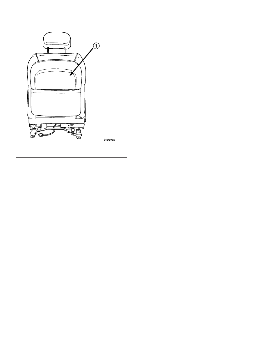
Fig. 27 FRONT SEAT BACK PANEL

1 - FRONT SEAT BACK PANEL

LH

RESTRAINTS

8O - 23

SEAT AIRBAG (Continued)

(5) Disengage seat back trim cover J-strap from

the upper, lower and airbag side of seat back.

(6) Disconnect the side airbag electrical connector.

Slide yellow locking tab down to unlock. Then with
two fingers, push two side retaining tabs in and pull
connector straight from side airbag.

(7) Remove the front seat cushion side shield.

Refer to Body, Seats, Front Seat Cushion Side Shield,
Removal.

(8) Disengage push pin and remove the wire har-

ness (Fig. 28) and (Fig. 29) from the seat assembly.

INSTALLATION

(1) Install the airbag wire harness in the seat. Be

certain the wire harness routing is correct. The har-
ness should follow the leading edge of the seat back
frame down into the lower seat cushion. Once
inserted in lower cushion, the harness is positioned
between the cushion pan and the seat track, and
held in place with push pins.

(2) Connect the side airbag electrical connector.

After connector is installed be certain the yellow
locking tab is in the upper “LOCKED” position.
Check to be certain that the connector cannot be
removed once yellow locking tab is positioned.

(3) Install the seat back trim cover J-straps on the

upper, lower, and airbag side of the seat back frame.

CAUTION: Always install new push pins when
installing the seat back plastic panel.

(4) Install the plastic back panel on the seat back.

Install new push pins in the upper mounting location
of the back cover. Refer to Body, Seats, Front Seat
Back Cover, Installation.

(5) Install the front seat cushion side shield. Refer

to Body, Seats, Front Seat Cushion Side Shield,
Installation.

WARNING: BE CERTAIN PLASTIC BACK COVER IS
SECURELY INSTALLED ON THE SEAT BACK. FAIL-
URE TO DO SO WILL ADVERSELY AFFECT THE
FUNCTIONALITY OF THE SIDE AIRBAG SYSTEM.

(6) Install the left front seat in the vehicle. Refer

to Body, Seats, Front Seat, Installation.

WARNING: DO NOT CONNECT THE BATTERY NEG-
ATIVE CABLE REMOTE TERMINAL. REFER TO
ELECTRICAL, RESTRAINTS, DIAGNOSIS AND TEST-
ING - AIRBAG SYSTEM FIRST.

Fig. 28 SEAT AIRBAG WIRE HARNESS LOCATION

1 - SEAT TRACK RETAINING BOLTS
2 - SEAT AIRBAG WIRE HARNESS
3 - SEAT AIRBAG WIRE HARNESS CONNECTOR
4 - CUSHION PAN

Fig. 29 SEAT AIRBAG WIRING HARNESS

1 - YELLOW CONNECTOR LOCK
2 - TO AIRBAG MODULE
3 - TO BODY HARNESS

8O - 24

RESTRAINTS

LH

SEAT AIRBAG WIRING HARNESS (Continued)

SEAT BELT BUCKLE - REAR
SEAT

REMOVAL

(1) Remove the rear seat cushion.
(2) Remove the seat belt anchor nut (Fig. 30).

(3) Remove the seat belt buckle from stud on floor.

INSTALLATION

(1) Place the seat belt buckle anchor over stud on

floor.

(2) Install the rear seat belt anchor nut. Tighten to

40 N·m (30 ft. lbs.) torque.

(3) Install the rear seat cushion.

SEAT BELT BUCKLE - FRONT
SEAT CENTER OCCUPIED -
CONCORDE/INTREPID

REMOVAL

(1) Move or remove the front seat as necessary to

gain access to seat belt buckle anchor bolt.

(2) Remove the bolt attaching buckle and rein-

forcement to front seat track (Fig. 31).

(3) Remove the seat belt buckle from vehicle.

INSTALLATION

(1) Place the seat belt buckle in position in the

vehicle.

(2) Install the buckle attaching bolt and reinforce-

ment to the front seat track or floor. Tighten bolt to
40 N·m (30 ft. lbs.) torque.

(3) Install the front seat, if it was removed.

Fig. 30 REAR SEAT BELT BUCKLE

1 - REAR SEAT BACK
2 - SEAT BELT BUCKLES
3 - ANCHOR

Fig. 31 FRONT SEAT CENTER OCCUPIED BELT

BUCKLE - REMOVE/INSTALL

1 - FRONT SEAT TRACK
2 - FRONT SEAT BELT BUCKLE

LH

RESTRAINTS

8O - 25

SIDE IMPACT AIRBAG
CONTROL MODULE

DESCRIPTION

Vehicles equipped with side impact airbags use two

Side Impact Airbag Control Modules (SIACM). One is
located on each respective side body B-pillar (Fig.
32).

OPERATION

Each Side Impact Airbag Control Module (SIACM)

serves as the impact sensor for its seat mounted air-
bag. The right side SIACM controls the right seat
airbag (Fig. 33). The left side SIACM controls the left
seat airbag (Fig. 33). Each SIACM contains two
accelerometers, both accelerometers must agree in
order to deploy the side airbag. In the event of a side
impact the appropriate SIACM will send a electronic
signal to its airbag, deploying the airbag. The SIACM
communicates with the occupant restraint controller
via the PCI bus circuit.

REMOVAL

(1) Disconnect and isolate the battery negative

cable remote terminal.

(2) Wait two minutes for the system reserve capac-

itor to discharge before servicing any airbag compo-
nents.

(3) Remove the lower B-pillar trim from the appro-

priate side of the vehicle. Refer to Body, Interior,
B-Pillar Lower Trim, Removal.

(4) Disconnect the side impact airbag control mod-

ule electrical connector (Fig. 32).

(5) Remove

the

SIACM

retaining

screws

and

remove the module from the vehicle (Fig. 32).

Fig. 32 SIACM POSITION/ORIENTATION

1 - VEHICLE BODY B-PILLAR
2 - SIDE IMPACT AIRBAG CONTROL MODULE (S.I.A.C.M.)
3 - S.I.A.C.M. ELECTRICAL CONNECTOR
4 - SEAT BELT RETRACTOR ASSEMBLY
5 - S.I.A.C.M. RETAINING SCREWS

8O - 26

RESTRAINTS

LH


Content   ..  109  110  111  112   ..