Chrysler 300M, Dodge Interpid. Manual - part 97


  Index      Chrysler     Chrysler 300M / Concorde / Interpid / LHS, Dodge Interpid - service repair manual 2000-2004 year


Search            


Content   ..  95  96  97  98   ..


Chrysler 300M, Dodge Interpid. Manual - part 97


ture can be obtained by enabling the EASY EXIT
SEAT 
feature and disabling the REMOTE LINKED
TO MEMORY 
feature. Then the EASY EXIT SEAT
feature will move the seat back, but the RKE unlock
event will not reposition the seat. Thus, the seat
remains positioned for easy entry, and the memory
switch on the door panel can be depressed after
entering the vehicle to return the seat to the desired
memory position.

• SIDE VIEW MIRROR TILT - This programma-

ble feature only applies to vehicles equipped with the
optional memory / heated system. The options
include Enable and Disable. The default is Disable.
When Enable is selected, both side view mirrors will
move straight downward anytime the MHSM module
detects a reverse gear indication from the cluster.
This feature is designed to allow the driver to see
directly behind the rear wheels before backing up.

• TRAIN REMOTE - When this feature is

selected the driver can choose to train up to four
remote

keyless

entry

transmitters.

The

options

include Yes and No. The default is No. When Yes is
selected and the MENU button is pressed the EVIC
will display “PRESS REMOTE LOCK & UNLOCK
THEN PRESS UNLOCK”, followed by a chime to
indicate the training sequence can commence. You
have approximately 30 seconds to train up to four
transmitters, after each transmitter is trained a
chime will sound indicating that the training was
successful. If remote link to memory is “YES” , the
first transmitter trained will be associated with
memory setting 1 and the second transmitter trained
will be associated with memory setting 2. Additional
transmitters will not be associated with a memory
setting. When you have finished training the trans-
mitters, press the menu button again and the EVIC
will display “TRAIN DONE “X” TRAINED. If no
transmitters are trained within approx. 30 seconds
the EVIC will display “TRAIN TIMEOUT”.

• RETRAIN TIRE SENSORS - This programma-

ble feature only applies to vehicles equipped with the
optional

Tire

Pressure

Monitoring

System.

The

options include Yes and No. The default is No. When
Yes is selected, and the menu button is depressed,
the EVIC will enter the training mode starting with
the left front tire.

REMOVAL - OVERHEAD CONSOLE

(1) Disconnect and isolate the remote negative bat-

tery cable.

(2) Remove the overhead console retaining screw,

located in the front of console near the windshield.

(3) Using your fingertips, grasp the sides of the

overhead console and pull straight down evenly to
disengage the two snap clips at the rear of the unit.

(4) Lower the overhead console far enough to

access the wire harness connectors.

(5) Disconnect the control module, courtesy lamps

and if equipped, the power sunroof switch electrical
connectors.

(6) Remove the overhead console assembly from

the vehicle.

INSTALLATION

(1) Position the overhead console in the vehicle

and connect the wire harness connectors.

(2) Connect the control module, courtesy lamps

and if equipped, the power sunroof switch electrical
connector.

(3) Using your fingertips, grasp the sides of the

overhead console and push straight up evenly to
engage the two snap clips at the rear of the unit.

(4) Install the overhead console retaining screw,

located in the front of console near the windshield.
Torque the screw to 1.2 N·m (10 in. lbs.).

(5) Connect the remote negative battery cable.
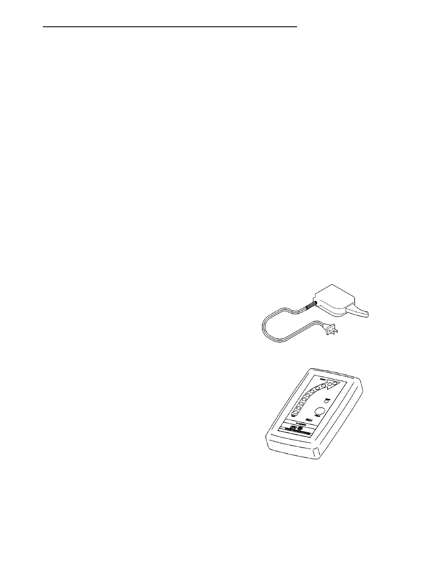
SPECIAL TOOLS

Degaussing Tool 6029

Radio Frequency Detector #9001

LH

MESSAGE SYSTEMS

8M - 7

OVERHEAD CONSOLE (Continued)

COMPASS/MINI-TRIP
COMPUTER

DESCRIPTION

The Compass Mini-Trip Computer (CMTC) is a

module located within the overhead console. This
module displays the following information:

• Compass/Temperature

• Average Fuel Economy

• Distance to Empty

• Trip Odometer

• Elapsed Time

• Miles to Service

• Tire Pressure Display (if equipped)

• Blank Screen
When the vehicle is first turned “ON” the Compass

Mini-Trip Computer blanks the display for a half sec-
ond, then Illuminates all segments of the vacuum
fluorescent display (VFD) at full brightness for one
and a half seconds. The Compass Mini-Trip Com-
puter module will then display whatever was being
viewed when the ignition was last turned “OFF”.

Compass Mini-Trip Computer may also be inte-

grated with the Universal Transmitter. If so, your
Compass Mini-Trip Computer module will have three
buttons centered together between the outer four
buttons. Refer to the photo in Overhead Console
description.

OPERATION

The Compass Mini-Trip Computer (CMTC) and

push buttons will only operate when the ignition is
in the ON position. The CMTC will show the last dis-
play when the ignition was turned OFF. The four
buttons used to operate Compass Mini-Trip Com-
puter are labeled STEP, C/T, US/M and RESET.

STEP BUTTON

Pressing the STEP button selects one the following

4 displays:

• Average fuel economy

• Distance to empty

• Trip odometer

• Elapsed time

C/T (COMPASS/TEMPERATURE) BUTTON

Pressing the C/T button selects the current Com-

pass heading or current Temperature display.

US/M (ENGLISH/METRIC MEASUREMENT) BUTTON

Pressing the US/M button switches the display

units in English or Metric readings.

RESET BUTTON

Pressing the RESET button resets the function

currently on the display, provided that function can
be reset. The functions which can be reset are Aver-
age fuel economy, Trip odometer and Elapsed time.
The RESET button is also used to set the variance
and/or calibrate the compass. Refer to the Variance
Procedure and Calibration Procedure in this section.

DIAGNOSIS AND TESTING - COMPASS
MINI-TRIP COMPUTER

TEMPERATURE

The Compass Mini-Trip Computer (CMTC) receives

Programmable Communications Interface bus (PCI
bus) messages from the Body Control Module for all
displayed information except the compass display. If
a dash (-) is displayed, the Compass Mini-Trip Com-
puter is not receiving a PCI bus message from the
BCM. To check out the PCI bus line and the BCM
use the DRB lll

t scan tool and proper Body Diagnos-

tic Procedure Manual.

If Compass Mini-Trip Computer displays a temper-

ature reading more than 54° C (130° F). Check for a
short circuit between the temperature sensor and the
BCM.

If Compass Mini-Trip Computer displays a temper-

ature reading less than -40° C (-67° F). Check for an
open circuit between the temperature sensor and the
BCM.

AVERAGE FUEL ECONOMY

Compass Mini-Trip Computer receives average fuel

economy information from the BCM over the PCI bus
line. If Compass Mini-Trip Computer displays -.-
instead of an average fuel economy value, it is not
receiving a PCI bus message for the average fuel
economy from the BCM. To check out the PCI bus
line and the BCM use the DRB lll

t scan tool.

DISTANCE TO EMPTY

Compass Mini-Trip Computer receives distance to

empty information from the BCM over the PCI bus
line. If Compass Mini-Trip Computer displays a dash
(-) instead of a distance to empty value, it is not
receiving a PCI bus message for the distance to
empty from the BCM. To check out the PCI bus line
and the BCM use the DRB lll

t scan tool.

8M - 8

MESSAGE SYSTEMS

LH

TRIP ODOMETER

Compass Mini-Trip Computer receives trip odome-

ter information from the Cluster over the PCI bus
line. If Compass Mini-Trip Computer displays dashes
-.- instead of the trip odometer value, it is not receiv-
ing a PCI bus message for the trip odometer from the
Cluster. To check out the PCI bus line and the BCM,
use the DRB lll

t scan tool.

ELAPSED TIME

Compass Mini-Trip Computer receives a PCI bus

message containing elapsed time information. If
Compass Mini-Trip Computer displays dashes -:--
instead of the elapsed time, it is not receiving a PCI
bus message for the elapsed time from the BCM. To
check out the PCI bus line and the BCM, use the
DRB lll

t scan tool.

COMPASS DISPLAY

To display the vehicle direction, the Compass Mini-

Trip Computer processes information from a sensor
internal to the module. The Compass Mini-Trip Com-
puter is self- calibrating and requires only variance
adjustments dependent upon location. The Compass
Mini-Trip Computer displays the label CAL whenever
the compass is in the fast calibration mode.

If all three of the following conditions listed below

occur, the vehicle must be demagnetized.

• Compass portion of the display is blank

• Temperature portion of the display is OK

• The label CAL is illuminated
If demagnetizing the vehicle is needed, refer to the

demagnetizing

procedure

in

this

section.

After

demagnetizing, to calibrate the compass refer to Cal-
ibration Procedure and to set the variance refer to
Variance Procedure, both within this section. If the
compass portion of the display is still blank, replace
the Compass Mini-Trip Computer.

COMPASS MINI-TRIP COMPUTER - SELF
DIAGNOSTIC TEST

(1) With the ignition switch in the OFF position

simultaneously press the C/T and STEP buttons and
hold.

(2) Turn ignition switch ON, then release C/T and

STEP buttons.

(3) Compass Mini-Trip Computer lights all seg-

ments on the VFD for 2-4 seconds. Check for seg-
ments that are not illuminated.

(4) If Compass Mini-Trip Computer displays PASS,

the module is OK.

(5) If Compass Mini-Trip Computer displays FAIL,

replace the module.

(6) If Compass Mini-Trip Computer displays bUS,

check for an open or a short in the PCI bus commu-
nication circuit.

(7) Press the C/T or the STEP button to exit self-

test.

REMOVAL

(1) Remove overhead console (Refer to 8 - ELEC-

TRICAL/OVERHEAD CONSOLE - REMOVAL).

(2) Remove mounting screws and release the map

lamp wire connector from the Compass Mini-Trip
Computer (Fig. 7).

(3) Remove the Compass Mini-Trip Computer from

overhead console.

INSTALLATION

(1) Position the Compass Mini-Trip Computer and

install the retaining screws.

(2) Connect the Compass Mini-Trip Computer elec-

trical connector. Make sure the wire that was clipped
into the module housing is properly clipped into the
new module before the overhead console is placed
back into the headliner.

(3) Install the overhead console (Refer to 8 -

ELECTRICAL/OVERHEAD CONSOLE - INSTALLA-
TION).

Fig. 7 Compass Mini-Trip Computer Retaining

Screws

1 - ILLUMINATION LAMPS
2 - CMTC RETAINING SCREWS

LH

MESSAGE SYSTEMS

8M - 9

COMPASS/MINI-TRIP COMPUTER (Continued)

ELECTRONIC VEHICLE INFO
CENTER

DESCRIPTION

The Electronic Vehicle Information Center (EVIC)

is

located

in

the

overhead

console

on

models

equipped with this option. The EVIC module features
a large Vacuum Fluorescent Display (VFD) screen for
displaying information, and back-lit push button
function switches labeled C/T (compass/temperature),
RESET, STEP, and MENU.

The EVIC module contains a central processing

unit and interfaces with other electronic modules in
the vehicle over the Programmable Communications
Interface (PCI) data bus network. The PCI data bus
network allows the sharing of sensor information.
This helps to reduce wire harness complexity, reduce
internal controller hardware, and reduce component
sensor current loads. At the same time, this system
provides increased reliability, enhanced diagnostics,
and allows the addition of many new feature capabil-
ities.

The EVIC includes the following display options:
• Compass and temperature - provides the out-

side temperature and one of eight compass readings
to indicate the direction the vehicle is facing.

• Average fuel economy - shows the average

fuel economy since the last trip computer reset.

• Distance to empty - shows the estimated dis-

tance that can be travelled with the fuel remaining
in the fuel tank. This estimated distance is computed
using the average miles-per-gallon from the last 30
gallons of fuel used.

• Trip odometer - shows the distance travelled

since the last trip computer reset.

• Elapsed time - shows the accumulated igni-

tion-on time since the last trip computer reset.

• Distance to service - shows the distance

remaining until the next scheduled service interval.

• Tire Pressure - shows tire pressure in each

road tire.

• Blank screen - the EVIC compass/temperature/

trip computer VFD is turned off.

The EVIC “Menu” push button provides the vehicle

operator with a user interface, which allows the
selection of several optional customer programmable
electronic features to suit individual preferences.
Refer to ELECTRONIC VEHICLE INFORMA-
TION CENTER PROGRAMMING 
in the Service
Procedures section of this group for more information
on the customer programmable feature options.

If the vehicle is equipped with the optional Univer-

sal Transmitter, the EVIC will also display messages
and an icon indicating when the Universal Transmit-
ter is being trained, which of the three transmitter

buttons is transmitting, and when the transceiver is
cleared.

If the vehicle is equipped with the optional Tire

Pressure Monitoring System, the EVIC will also
display messages and an icon indicating when the
tire air pressure falls below a given set-point, and
which of the five tires is transmitting the low pres-
sure warning, and when the condition is cleared.
Refer to the Tires/Wheels section of this manual for
complete Tire Pressure Monitoring System descrip-
tion. Refer to this section of the service manual for
EVIC modules function description for the Tire Pres-
sure Monitoring.

NOTE: Some 300M vehicles use a different recom-
mended tire pressure (tire specified). For this rea-
son, anytime a EVIC module is removed or replaced
a DRB III

T

scan tool must be used to set/verify that

the correct tire pressure set-point is programmed in
the EVIC module. Failure to do so could result in
incorrect tire pressure monitoring set points.

Data input for all EVIC functions, including VFD

dimming level, is received through PCI data bus
messages. The EVIC module uses its internal pro-
gramming and all of its data inputs to calculate and
display the requested data. If the data displayed is
incorrect,

perform

the

self-diagnostic

tests

as

described in this group. If these tests prove inconclu-
sive, the use of a DRB III

t scan tool and the proper

Diagnostic Procedures manual are recommended for
further testing of the EVIC module and the PCI data
bus.

The EVIC module cannot be repaired, and is avail-

able for service only as a unit. This unit includes the
push button switches and the plastic module. If any
of these components is faulty or damaged, the com-
plete EVIC module must be replaced. The incandes-
cent bulbs used for EVIC push button back-lighting
and the lens are available for service replacement.

DESCRIPTION - COMPASS

While in the compass/temperature mode, the com-

pass will display the direction in which the vehicle is
pointed using the eight major compass headings
(Examples: north is N, northeast is NE). The self-cal-
ibrating compass unit requires no adjusting in nor-
mal use. The only calibration that may prove
necessary is to drive the vehicle in three complete
circles at 5 to 8 kilometers-per-hour (3 to 5 miles-per-
hour), on level ground, in not less than forty-eight
seconds. This will reorient the compass unit to its
vehicle.

The compass unit also will compensate for magne-

tism the body of the vehicle may acquire during nor-
mal use. However, avoid placing anything magnetic
directly on the roof of the vehicle. Magnetic mounts

8M - 10

MESSAGE SYSTEMS

LH


Content   ..  95  96  97  98   ..