Chrysler 300M, Dodge Interpid. Manual - part 80


  Index      Chrysler     Chrysler 300M / Concorde / Interpid / LHS, Dodge Interpid - service repair manual 2000-2004 year


Search            


Content   ..  78  79  80  81   ..


Chrysler 300M, Dodge Interpid. Manual - part 80


AUTO SHUT DOWN RELAY

DESCRIPTION

The relay is located in the Power Distribution Cen-

ter (PDC) (Fig. 1). For the location of the relay
within the PDC, refer to the PDC cover for location.
Check electrical terminals for corrosion and repair as
necessary.

OPERATION

The ASD sense circuit (SBEC vehicles) or the

engine switched battery (NGC vehicles) informs the
PCM when the ASD relay energizes. A 12 volt signal
at this input indicates to the PCM that the ASD has
been activated. This input is also used to power cer-
tain drivers on NGC vehicles.

When energized, the ASD relay on SBEC vehicles

supplies battery voltage to the fuel injectors, ignition
coils and the heating element in each oxygen sensor.

When energized, the ASD relay on NGC vehicles

provides power to operate the injectors, ignition coil,
generator field, O2 sensor heaters (both upstream
and downstream), evaporative purge solenoid, EGR
solenoid

(if

equipped)

wastegate

solenoid

(if

equipped), and NVLD solenoid (if equipped).

For both SBEC and NGC vehicles, the ASD relay

also provides a sense circuit to the PCM for diagnos-
tic purposes. If the PCM does not receive 12 volts
from this input after grounding the control side of
the ASD relay, it sets a Diagnostic Trouble Code
(DTC). The PCM energizes the ASD any time there is
an engine speed that exceeds a predetermined value
(typically about 50 rpm). The ASD relay can also be
energized after the engine has been turned off to per-
form an O2 sensor heater test, if vehicle is equipped
with OBD II diagnostics.

As mentioned earlier, the PCM energizes the ASD

relay during an O2 sensor heater test. This test is
performed only after the engine has been shut off for
SBEC vehicles. On NGC vehicles it checks the O2
heater upon vehicle start. The PCM still operates
internally to perform several checks, including moni-
toring the O2 sensor heaters.

CAMSHAFT POSITION
SENSOR

DESCRIPTION

The camshaft position sensor is mounted in the

front of the head on 2.7L (Fig. 2) or belt cover on the
3.5L (Fig. 3). It is a hall effect device.

Fig. 1 Power Distribution Center (PDC)

1 - PDC COVER
2 - PDC

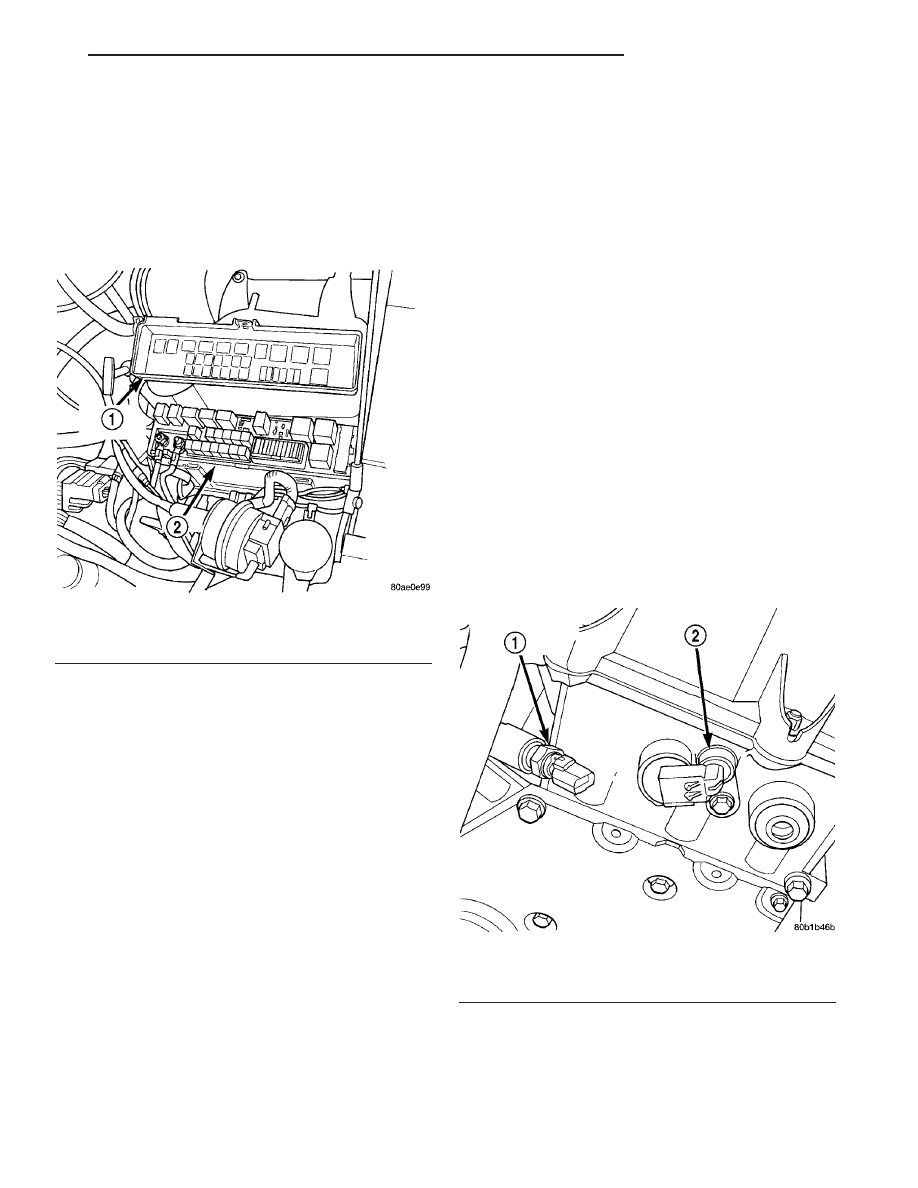
Fig. 2 Camshaft Position Sensor - 2.7L

1 - ENGINE COOLANT TEMPERATURE SENSOR
2 - CAMSHAFT POSITION SENSOR

LH

IGNITION CONTROL

8I - 3

OPERATION

The camshaft position sensor contains a hall effect

device that provide cylinder identification to the Pow-
ertrain Control Module (PCM) (Fig. 4) or (Fig. 5).
The sensor generates pulses as groups of notches on
the camshaft sprocket pass underneath it. The PCM
keeps track of crankshaft rotation and identifies each
cylinder by the pulses generated by the notches on
the camshaft sprocket.

When metal aligns with the sensor, voltage goes

low (less than 0.3 volts). When a notch aligns with
the sensor, voltage spikes high (5.0 volts). As a group
of notches pass under the sensor, the voltage
switches from low (metal) to high (notch) then back
to low. The number of notches determine the amount
of pulses. If available, an oscilloscope or DRBIII

t

PEP Module can display the square wave patterns of
each timing event.

REMOVAL

REMOVAL - 2.7L

The camshaft position sensor is mounted in the

front of the head.

(1) Disconnect electrical connector from sensor.
(2) Remove camshaft position sensor screw.
(3) Without pulling on the connector, pull the sen-

sor out of the chain case cover.

REMOVAL - 3.5L

The camshaft position sensor is installed in the

timing belt housing cover above the left camshaft
sprocket.

(1) Disconnect the negative battery cable.
(2) Loosen the upper intake plenum, refer to the

Intake System section.

(3) Disconnect electrical connector from sensor.
(4) Remove camshaft position sensor screw.
(5) Pull sensor up out of the timing belt housing

cover.

INSTALLATION

INSTALLATION - 2.7L

The camshaft position sensor is mounted in the

front of the head.

(1) Install sensor in the chain case cover and push

sensor in until contact is made with the boss on the
head. While holding the sensor in this position,

Fig. 3 CAMSHAFT POSITION SENSOR LOCATION

3.5L

1 - CAMSHAFT SENSOR

Fig. 4 Camshaft Position Sensor 2.7L

Fig. 5 Camshaft Position Sensor 3.5L

8I - 4

IGNITION CONTROL

LH

CAMSHAFT POSITION SENSOR (Continued)

install and tighten the retaining bolt to 12 N·m (105
in. lbs.) torque.

(2) Attach electrical connector to sensor.

INSTALLATION - 3.5L

The camshaft position sensor is installed in the

timing belt housing cover above the left camshaft
sprocket.

If the removed sensor is reinstalled, com-

pletely remove the old spacer from the sensor
face. Attach a NEW SPACER to the face of the
sensor before installation. 
If installing a new sen-
sor, confirm that the paper spacer is attached to the
face (Fig. 6).

(1) Install sensor in the timing belt housing and

push sensor down until contact is made with the
camshaft sprocket. While holding the sensor in this
position, install and tighten the retaining bolt to 12
N·m (105 in. lbs.) torque.

(2) Attach electrical connector to sensor.
(3) Install the upper intake plenum, refer to the

Intake System section.

(4) Connect the negative battery cable.

IGNITION COIL

DESCRIPTION

The engines are equipped with a coil on plug igni-

tion system (Fig. 7) or (Fig. 8). Each cylinder has a
dedicated coil that sits atop each plug. No secondary
wires are required and connection from the coil to
plug is made with a boot that is attached to the coil.
The combination of the coil, boot, and fasteners is
known as the ignition coil assembly. The Powertrain
Control Module (PCM) determines which coil to
charge and fire at the correct time.

OPERATION

The Auto Shutdown (ASD) relay provides battery

voltage to the ignition coil. The PCM provides a
ground contact (circuit) for energizing the coil. When
the PCM breaks the contact, the energy in the coil
primary transfers to the secondary causing the
spark. The PCM will de-energize the ASD relay if it
does not receive the crankshaft position sensor and
camshaft position sensor inputs. For limp home capa-
bility, the engine can run on crankshaft sensor or
camshaft sensor. Refer to Auto Shutdown (ASD)
Relay—PCM Output, in this section for relay opera-
tion.

Fig. 6 Paper Spacer 3.5L

1 - CAMSHAFT POSITION SENSOR
2 - PAPER SPACER

Fig. 7 Ignition Coil - 2.7L

Fig. 8 Ignition Coil - 3.5L

LH

IGNITION CONTROL

8I - 5

CAMSHAFT POSITION SENSOR (Continued)

The coil’s low primary resistance (0.4 - 0.6 ohm)

allows the PCM to fully charge the coil for each fir-
ing. There is a coil capacitor added to each bank of
cylinders for the 2.7L and the left bank of the 3.5L
for radio noise suppression (Fig. 9).

REMOVAL

(1) Prior to removing the ignition coils, spray com-

pressed air around the coil area and spark plug.

(2) Remove electrical connector from ignition coil.
On 3.5L engines, it is necessary to loosen the

screws by alternating back and forth. Do not lose the
spacers under the coil when loosening the screws.

(3) Remove 2 fasteners from ignition coil assembly.
(4) Remove ignition coil assembly.

INSTALLATION

(1) Install ignition coil assembly for spark plug.
(2) Install coil screws and tighten: 2.7L engine to

6.2 N·m (55 in. lbs.), 3.5L engines to 6.7 N·m (60 in.
lbs.).

(3) Connect the electrical connector.

IGNITION COIL CAPACITOR

DESCRIPTION

The Auto Shutdown (ASD) relay provides battery

voltage to the ignition coil. The PCM provides a
ground contact (circuit) for energizing the coil. When
the PCM breaks the contact, the energy in the coil
primary transfers to the secondary causing the
spark. The PCM will de-energize the ASD relay if it
does not receive the crankshaft position sensor and
camshaft position sensor inputs. For limp home capa-

bility, the engine can run on crankshaft sensor or
camshaft sensor. Refer to Auto Shutdown (ASD)
Relay—PCM Output, in this section for relay opera-
tion.

The coil’s low primary resistance (0.4 - 0.6 ohm)

allows the PCM to fully charge the coil for each fir-
ing. There is a coil capacitor for radio noise suppres-
sion (Fig. 10).

REMOVAL

(1) Remove the negative battery cable.
(2) Disconnect the electrical connector (Fig. 11).
(3) Remove nut and capacitor.

Fig. 9 COIL CAPACITOR

1 - IGNITION COIL CAPACITOR

Fig. 10 COIL CAPACITOR

1 - IGNITION COIL CAPACITOR

Fig. 11 COIL CAPACITOR

1 - IGNITION COIL CAPACITOR

8I - 6

IGNITION CONTROL

LH

IGNITION COIL (Continued)


Content   ..  78  79  80  81   ..