Chrysler 300M, Dodge Interpid. Manual - part 33


  Index      Chrysler     Chrysler 300M / Concorde / Interpid / LHS, Dodge Interpid - service repair manual 2000-2004 year


Search            


Content   ..  31  32  33  34   ..


Chrysler 300M, Dodge Interpid. Manual - part 33


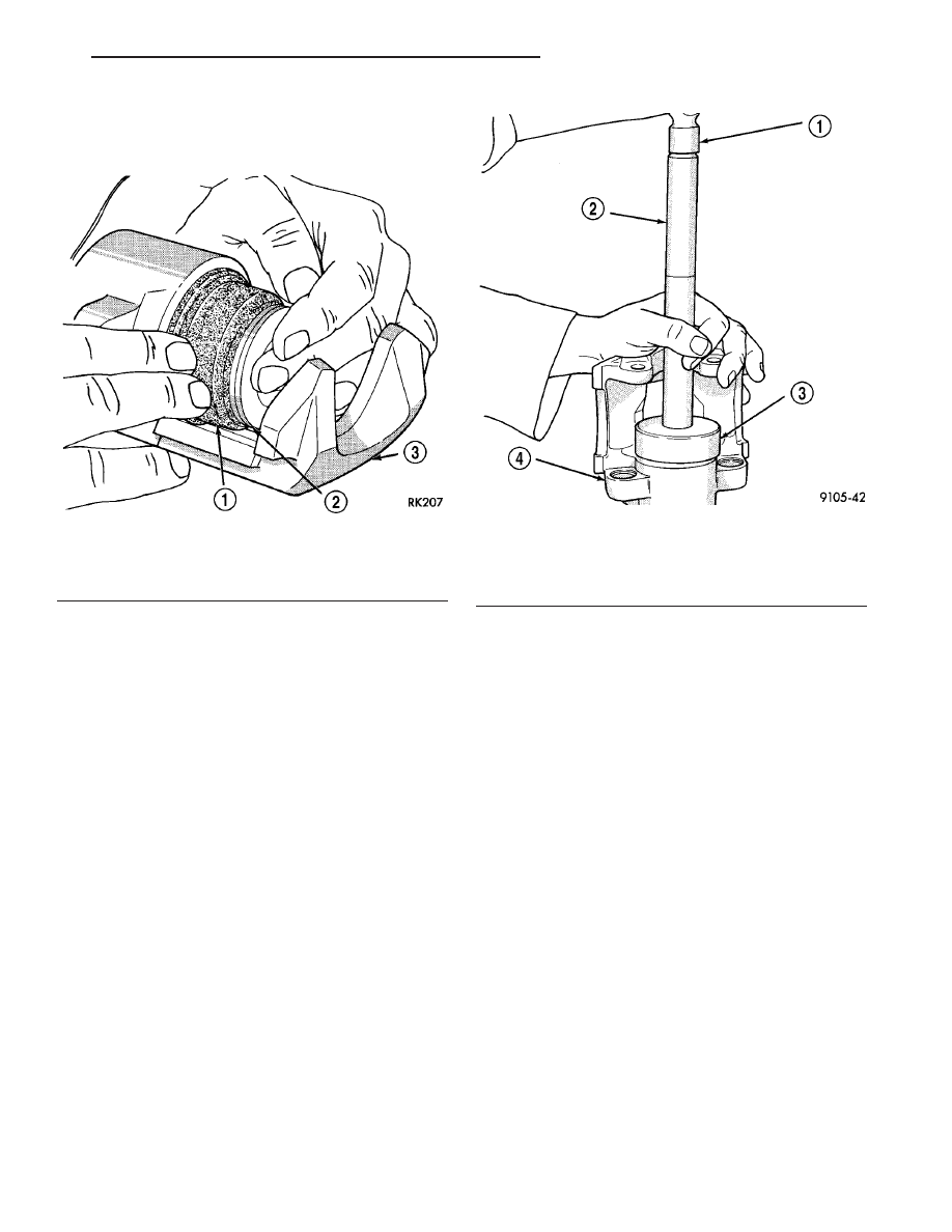
(4) Install piston into caliper bore pushing it past

the piston seal until it bottoms in the caliper bore
(Fig. 38).

(5) Position the dust boot into the counterbore of

the caliper assembly piston bore.

(6) Using a hammer and Installer, Special Tool

C-4689 or C-4842 (depending on piston size), and
Handle, Special Tool C-4171, drive the boot into the
counterbore of the caliper as necessary (Fig. 39).

(7) Reinstall the caliper on the vehicle and bleed

the brakes as necessary. Refer to Installation in this
section.

INSTALLATION

INSTALLATION - FRONT CALIPER

CAUTION: Use care when installing the caliper
assembly on the steering knuckle, so seals on cal-
iper guide pin bushings do not get damaged by the
steering knuckle bosses.

(1) Completely retract the caliper piston back into

the piston bore of the caliper.

(2) If removed, install brake rotor on hub (Fig. 26).
(3) Lubricate both machined knuckle abutments

with a liberal amount of Mopar

t Brake Grease For

Caliper Slides Lubricant, or equivalent.

(4) Install one rail shim on each machined abut-

ment where it will contact the brake shoes. Make
sure the alignment tabs on the shims are positioned
toward the abutments.

(5) Carefully position caliper and brake shoes over

rotor by reversing removal procedure (Fig. 25).

CAUTION: When being installed, extreme caution
should be taken not to crossthread the caliper
guide pin bolts.

(6) Install the caliper guide pin bolts. Tighten

guide pin bolts to a torque of 22 N·m (192 in. lbs.).

(7) Install the banjo bolt connecting the flex hose

to the caliper. One washer should be installed on
each side of the flex hose fitting before installing the
banjo bolt. Tighten banjo bolt to a torque of 48 N·m
(35 ft. lbs.).

(8) Install the wheel and tire assembly.
(9) Tighten the wheel mounting stud nuts in

proper sequence until all nuts are torqued to half
specification. Then repeat the tightening sequence to
the full specified torque of 135 N·m (100 ft. lbs.).

(10) Lower vehicle.

CAUTION: After performing any service to the vehi-
cle brake system, be sure to obtain a firm brake
pedal before moving vehicle.

(11) Remove the brake pedal holding tool.
(12) Bleed the base brakes. (Refer to 5 - BRAKES -

BASE - STANDARD PROCEDURE)

Fig. 38 Installing Piston Into Caliper Bore

1 - BOOT
2 - PISTON
3 - CALIPER

Fig. 39 Installing Dust Boot

1 - HAMMER
2 - SPECIAL TOOL C-4171
3 - SPECIAL TOOL C-4689 or C-4842
4 - CALIPER

LH

BRAKES - BASE BRAKE SYSTEM

5 - 27

DISC BRAKE CALIPER - FRONT (Continued)

(13) Road test the vehicle and make several stops

to wear off any foreign material off the brakes and to
seat the brake shoe linings.

INSTALLATION - FRONT CALIPER (EXPORT)

CAUTION: Use care when installing the caliper
assembly on the steering knuckle, so seals on cal-
iper guide pin bushings do not get damaged by the
steering knuckle bosses.

(1) Completely retract the caliper piston back into

the piston bore of the caliper.

(2) If removed, install brake rotor on hub (Fig. 26).
(3) Lubricate both machined knuckle abutments

with a liberal amount of Mopar

t Brake Grease For

Caliper Slides Lubricant, or equivalent.

(4) Carefully position caliper and brake shoes over

rotor by reversing removal procedure (Fig. 25).

CAUTION: When being installed, extreme caution
should be taken not to crossthread the caliper
guide pin bolts.

(5) Install the caliper guide pin bolts. Tighten

guide pin bolts to a torque of 22 N·m (192 in. lbs.).

(6) Install the banjo bolt connecting the flex hose

to the caliper. One washer should be installed on
each side of the flex hose fitting before installing the
banjo bolt. Tighten banjo bolt to a torque of 48 N·m
(35 ft. lbs.).

(7) Install the wheel and tire assembly.
(8) Tighten the wheel mounting stud nuts in

proper sequence until all nuts are torqued to half
specification. Then repeat the tightening sequence to
the full specified torque of 135 N·m (100 ft. lbs.).

(9) Lower vehicle.

CAUTION: After performing any service to the vehi-
cle brake system, be sure to obtain a firm brake
pedal before moving vehicle.

(10) Remove the brake pedal holding tool.
(11) Bleed the base brakes. (Refer to 5 - BRAKES -

STANDARD PROCEDURE)

(12) Road test the vehicle and make several stops

to wear off any foreign material off the brakes and to
seat the brake shoe linings.

DISC BRAKE CALIPER - REAR

REMOVAL- REAR CALIPER

(1) Raise vehicle on jackstands or centered on a

hoist. See Hoisting in the Lubrication and Mainte-
nance section of this manual.

(2) Remove rear wheel and tire assemblies from

vehicle.

(3) Remove the 2 caliper assembly to adapter

guide pin bolts (Fig. 40).

(4) Remove caliper from adapter using following

procedure. First rotate top of caliper away from
adapter. Then lift the caliper off the bottom abut-
ment on the adapter (Fig. 41).

Fig. 40 Removing Caliper Guide Pin Bolts

1 - CALIPER ASSEMBLY
2 - ADAPTER
3 - CALIPER ASSEMBLY ATTACHING BOLT
4 - CALIPER ASSEMBLY ATTACHING BOLT

Fig. 41 Removing / Installing Caliper Assembly

1 - ADAPTER
2 - BRAKING DISC
3 - CALIPER ASSEMBLY
4 - ADAPTER ABUTMENT

5 - 28

BRAKES - BASE BRAKE SYSTEM

LH

DISC BRAKE CALIPER - FRONT (Continued)

(5) Support caliper assembly firmly from rear strut

to prevent weight of caliper from damaging the flex-
ible brake hose (Fig. 42).

(6) Remove the rear rotor from hub by pulling it

straight off the wheel mounting studs (Fig. 43).

DISASSEMBLY

DISASSEMBLY - CALIPER GUIDE PIN
BUSHINGS

Before disassembling the brake caliper, clean and

inspect it. Refer to CLEANING or INSPECTION in
this section.

(1) With one hand, push the guide pin bushing

sleeve towards the back of the caliper, and at the
same time, pull the sleeve out the back of the caliper
and bushing (Fig. 44).

Fig. 42 Storing Caliper

1 - FLEX HOSE
2 - STRUT
3 - WIRE HANGER
4 - CALIPER ASSEMBLY

Fig. 43 Removing / Installing Rear Rotor

1 - BRAKE ROTOR (DISC)
2 - DISC SHIELD
3 - HUB
4 - DRUM-IN-HAT PARKING BRAKE

Fig. 44 Removing Sleeve From Bushing

1 - CALIPER
2 - SLEEVE
3 - BUSHING

LH

BRAKES - BASE BRAKE SYSTEM

5 - 29

DISC BRAKE CALIPER - REAR (Continued)

(2) Using your fingers, collapse one side of the rub-

ber guide pin bushing. Pull the guide pin bushing out
the other side of the brake caliper mounting boss
(Fig. 45).

DISASSEMBLY - CALIPER PISTON AND SEAL

WARNING: UNDER NO CONDITION SHOULD HIGH
PRESSURE AIR EVER BE USED TO REMOVE A PIS-
TON FROM A CALIPER BORE. PERSONAL INJURY
COULD RESULT FROM SUCH A PRACTICE.

NOTE: Before disassembling the brake caliper,
clean and inspect it. Refer to CLEANING AND
INSPECTION in this section.

NOTE: The safest way to remove the piston from
the caliper bore is to use the hydraulic pressure of
the vehicle’s brake system.

(1) Following the removal procedure in DISC

BRAKE SHOES found in this section, remove the
caliper from the brake rotor and hang the assembly
on a wire hook away from rotor and body of the vehi-
cle so brake fluid cannot get on these components.
Remove the brake shoes, and place a small piece of
wood between the piston and caliper fingers.

(2) Carefully depress the brake pedal to hydrauli-

cally push piston out of its bore. Once completed,
apply and hold down the brake pedal to any position

beyond the first inch of pedal travel using a brake
pedal holding tool. This will prevent the fluid in the
master cylinder reservoir from completely draining
out.

(3) Disconnect the brake fluid flex hose from the

caliper assembly and remove it from the vehicle.

CAUTION: Do not use excessive force when clamp-
ing caliper in vise. Excessive vise pressure will
cause bore distortion.

(4) Mount the caliper in a vise equipped with pro-

tective jaws.

(5) Remove the piston dust boot from the caliper

and discard (Fig. 46).

NOTE: Do not use a screw driver or other metal tool
for seal removal. Using such tools can scratch the
bore or leave burrs on the seal groove edges.

(6) Using a soft tool such as a plastic trim stick,

work the piston seal out of its groove in caliper pis-
ton bore (Fig. 47). Discard the old seal.

(7) Clean the piston bore and drilled passage ways

using alcohol or a suitable solvent. Wipe it dry using
only a lint-free cloth.

(8) Inspect the piston bore for scoring or pitting.

Bores that show light scratches or corrosion can usu-
ally be cleared of the light scratches or corrosion
using crocus cloth. Bores that have deep scratches or
scoring should be honed. Use Caliper Hone, Special

Fig. 45 Removing Bushing From Caliper

1 - CALIPER
2 - BUSHING

Fig. 46 Removing Caliper/Piston Dust Boot

1 - CALIPER
2 - SCREWDRIVER
3 - BOOT

5 - 30

BRAKES - BASE BRAKE SYSTEM

LH

DISC BRAKE CALIPER - REAR (Continued)


Content   ..  31  32  33  34   ..