Chrysler 300M, Dodge Interpid. Manual - part 30


  Index      Chrysler     Chrysler 300M / Concorde / Interpid / LHS, Dodge Interpid - service repair manual 2000-2004 year


Search            


Content   ..  28  29  30  31   ..


Chrysler 300M, Dodge Interpid. Manual - part 30


BRAKE PADS/SHOES - FRONT

REMOVAL

REMOVAL - FRONT DISC BRAKE SHOES

(1) Raise vehicle. (Refer to LUBRICATION &

MAINTENANCE/HOISTING - STANDARD PROCE-
DURE)

(2) Remove front wheel and tire assemblies from

vehicle.

(3) Remove the two caliper guide pin bolts (Fig.

11).

NOTE: Note the positioning of the two rail shims
between the knuckle’s machined abutments and the
brake shoes.

(4) Remove

caliper

assembly

from

steering

knuckle. Proceed by first rotating top of caliper away
from steering knuckle, then lifting caliper off bottom
machined abutment on steering knuckle (Fig. 12).
Take care not to lose the two rail shims.

(5) Hang the caliper off to the side using wire or

bungee cord (Fig. 13). Do not allow the caliper to be
supported by the flexible brake hose. Damage to the
flexible brake hose may result.

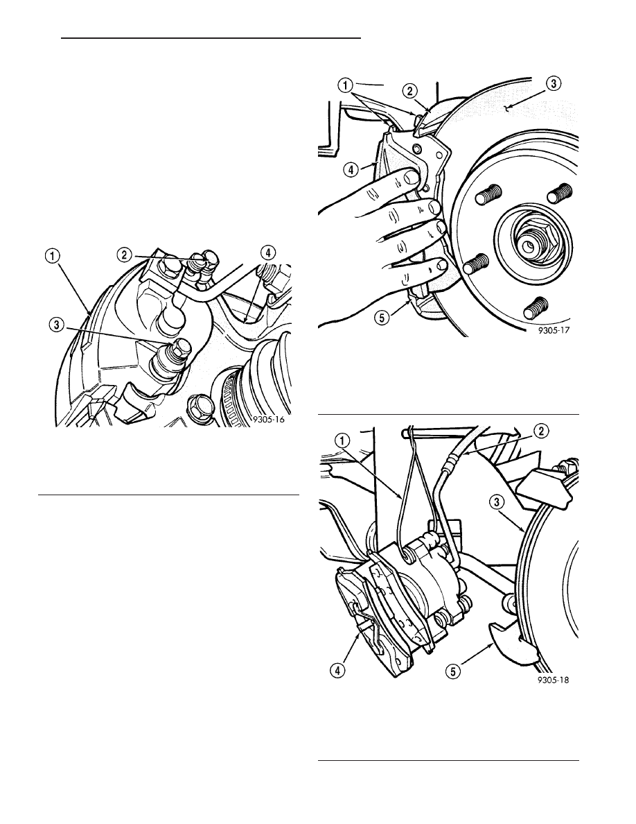
Fig. 11 Caliper Guide Pin Bolts

1 - CALIPER ASSEMBLY
2 - GUIDE PIN BOLT
3 - GUIDE PIN BOLT
4 - STEERING KNUCKLE

Fig. 12 Caliper Removal/Installation

1 - BRAKE SHOES
2 - STEERING KNUCKLE
3 - BRAKING DISC
4 - CALIPER ASSEMBLY
5 - MACHINED ABUTMENT

Fig. 13 Supported Caliper

1 - WIRE HANGER
2 - FLEXIBLE BRAKE HOSE
3 - BRAKING DISC
4 - CALIPER ASSEMBLY
5 - STEERING KNUCKLE

LH

BRAKES - BASE BRAKE SYSTEM

5 - 15

(6) Remove outboard brake shoe by prying the

shoe retaining clip over raised area on caliper. Then
slide the brake shoe off the caliper (Fig. 14).

(7) Pull inboard brake shoe away from piston until

retaining clip is free from cavity in piston (Fig. 15).

(8) Repeat steps (3) through (7) on opposite side of

vehicle to remove that sides brake shoes.

REMOVAL - FRONT DISC BRAKE SHOES
(EXPORT)

(1) Raise vehicle. (Refer to LUBRICATION &

MAINTENANCE/HOISTING - STANDARD PROCE-
DURE)

(2) Remove both front wheel and tire assemblies

from vehicle.

(3) Remove the two caliper guide pin bolts (Fig.

11).

(4) Remove

caliper

assembly

from

steering

knuckle. Proceed by first rotating top of caliper away
from steering knuckle and then lifting caliper off bot-
tom machined abutment on steering knuckle (Fig.
12).

(5) Hang the caliper off to the side using wire or

bungee cord (Fig. 13). Do not allow the caliper to be
supported by the flexible brake hose. Damage to the
flexible brake hose may result.

(6) Remove outboard brake shoe by prying the

shoe retaining clip over raised area on caliper. Then
slide the brake shoe off the caliper (Fig. 14).

(7) Pull inboard brake shoe away from piston until

retaining clip is free from cavity in piston (Fig. 15).

(8) Repeat steps (3) through (7) on opposite side of

vehicle to remove that sides brake shoes.

CLEANING - DISC BRAKE SHOES

WARNING: DUST AND DIRT ACCUMULATING ON
BRAKE PARTS DURING NORMAL USE MAY CON-
TAIN ASBESTOS FIBERS FROM PRODUCTION OR
AFTERMARKET

BRAKE

LININGS.

BREATHING

EXCESSIVE

CONCENTRATIONS

OF

ASBESTOS

FIBERS CAN CAUSE SERIOUS BODILY HARM.
EXERCISE

CARE

WHEN

SERVICING

BRAKE

PARTS. DO NOT SAND OR GRIND BRAKE LINING
UNLESS EQUIPMENT USED IS DESIGNED TO CON-
TAIN THE DUST RESIDUE. DO NOT CLEAN BRAKE
PARTS

WITH

COMPRESSED AIR

OR

BY DRY

BRUSHING. CLEANING SHOULD BE DONE BY
DAMPENING THE BRAKE COMPONENTS WITH A
FINE MIST OF WATER, THEN WIPING THE BRAKE
COMPONENTS CLEAN WITH A DAMPENED CLOTH.
DISPOSE OF CLOTH AND ALL RESIDUE CONTAIN-
ING ASBESTOS FIBERS IN AN IMPERMEABLE
CONTAINER WITH THE APPROPRIATE LABEL. FOL-
LOW PRACTICES PRESCRIBED BY THE OCCUPA-
TIONAL SAFETY AND HEALTH ADMINISTRATION
(OSHA) AND THE ENVIRONMENTAL PROTECTION
AGENCY (EPA) FOR THE HANDLING, PROCESSING,
AND DISPOSING OF DUST OR DEBRIS THAT MAY
CONTAIN ASBESTOS FIBERS.

Fig. 14 Removing Outboard Brake Shoe

1 - RETAINING CLIP
2 - CALIPER ASSEMBLY
3 - BRAKE SHOE

Fig. 15 Inboard Brake Shoe

1 - PISTON
2 - BRAKE SHOE
3 - CALIPER ASSEMBLY

5 - 16

BRAKES - BASE BRAKE SYSTEM

LH

BRAKE PADS/SHOES - FRONT (Continued)

INSPECTION - DISC BRAKE SHOES

Visually inspect brake shoes (pads) for uneven lining

wear. Also inspect for excessive lining deterioration.
Check the clearance between the tips of the wear indi-
cators on the shoes (if equipped) and the brake rotors.

If a visual inspection does not adequately deter-

mine the condition of the lining, a physical check will
be necessary. To check the amount of lining wear,
remove the disc brake shoes from the calipers.

Measure each brake shoe. The combined brake

shoe and its lining material thickness should be mea-
sured at its thinnest point.

• For front disc brake shoes, when a set of brake

shoes are worn to a thickness of approximately 7.95
mm (5/16 inch), they should be replaced.

• For rear disc brake shoes, when a set of brake

shoes are worn to a thickness of approximately 7.0
mm (9/32 inch), they should be replaced.

• Typically, if front shoes are worn out, both fronts

and rears need to be replaced. Make sure to check rears.

Replace both disc brake shoes (inboard and out-

board) on each caliper. It is necessary to replace the
shoes on the opposite side of the vehicle as well as
the shoes failing inspection.

If the brake shoe assemblies do not require

replacement, be sure to reinstall the brake shoes in
the original position they were removed from.

INSTALLATION

INSTALLATION - FRONT DISC BRAKE SHOES

(1) Completely retract caliper piston back into pis-

ton bore of caliper assembly.

(2) Lubricate both steering knuckle abutments

with a liberal amount of Mopar

t Brake Grease For

Caliper Slides Lubricant, or equivalent.

(3) Remove the protective paper from the noise

suppression gasket on both the inner and outer brake
shoe assemblies (if equipped).

NOTE: The inboard and outboard brake shoes are
not common, refer to (Fig. 16) for inboard and out-
board brake shoe assembly identification.

NOTE: When installing inboard brake shoe into cal-
iper piston, be sure brake shoe is positioned
squarely against the face of the caliper piston.

(4) Install the new inboard brake shoe assembly

into the caliper piston by firmly pressing it into bore
of caliper piston with thumbs (Fig. 15).

(5) Slide the new outboard brake shoe assembly

onto the caliper assembly (Fig. 17).

(6) Install one rail shim on each machined abut-

ment where it will contact the brake shoes. Make

sure the alignment tabs on the shims are positioned
toward the abutments.

(7) Carefully position caliper and brake shoes over

rotor by reversing the removal procedure (Fig. 12).

CAUTION: When being installed, extreme caution
should be taken not to crossthread the caliper
guide pin bolts.

(8) Install the caliper guide pin bolts (Fig. 11). Tighten

guide pin bolts to a torque of 22 N·m (192 in. lbs.).

(9) Repeat the preceding steps on the opposite side

of the vehicle, installing the brake shoes on that side
of the vehicle.

(10) Install the wheel and tire assemblies.

Fig. 16 Inboard And Outboard Shoes

1 - INBOARD BRAKE SHOE
2 - WEAR INDICATOR
3 - OUTBOARD BRAKE SHOE

Fig. 17 Installing Outboard Brake Shoe Assembly

1 - BRAKE SHOE ASSEMBLY
2 - BRAKE CALIPER

LH

BRAKES - BASE BRAKE SYSTEM

5 - 17

BRAKE PADS/SHOES - FRONT (Continued)

(11) Tighten the wheel mounting stud nuts in

proper sequence until all nuts are torqued to half
specification. Then repeat the tightening sequence to
the full specified torque of 135 N·m (100 ft. lbs.).

(12) Lower vehicle.

CAUTION: After performing any service to the vehi-
cle brake system, be sure to obtain a firm brake
pedal before moving vehicle.

(13) Pump the brake pedal several times to ensure

the vehicle has a firm brake pedal to adequately stop
vehicle.

(14) Check and adjust the brake fluid level as nec-

essary.

(15) Road test the vehicle and make several stops

to wear off any foreign material on the brakes and to
seat the brake shoe linings.

INSTALLATION - FRONT DISC BRAKE SHOES
(EXPORT)

(1) Completely retract caliper piston back into pis-

ton bore of caliper assembly.

(2) Lubricate both steering knuckle abutments

with a liberal amount of Mopar

t Brake Grease For

Caliper Slides Lubricant, or equivalent.

(3) Remove the protective paper from the noise

suppression gasket on both the inner and outer brake
shoe assemblies (if equipped).

NOTE: The inboard and outboard brake shoes are
not common, refer to (Fig. 16) for inboard and out-
board brake shoe assembly identification.

NOTE: When installing inboard brake shoe into cal-
iper piston, be sure brake shoe is positioned
squarely against the face of the caliper piston.

(4) Install the new inboard brake shoe assembly

into the caliper piston by firmly pressing it into bore
of caliper piston with thumbs (Fig. 15).

(5) Slide the new outboard brake shoe assembly

onto the caliper assembly (Fig. 17).

(6) Carefully position caliper and brake shoes over

rotor by reversing the removal procedure (Fig. 12).

CAUTION: When being installed, extreme caution
should be taken not to crossthread the caliper
guide pin bolts.

(7) Install the caliper guide pin bolts (Fig. 11).

Tighten guide pin bolts to a torque of 22 N·m (192 in.
lbs.).

(8) Repeat the preceding steps on the opposite side

of the vehicle, installing the brake shoes on that side
of the vehicle.

(9) Install the wheel and tire assemblies.
(10) Tighten the wheel mounting stud nuts in

proper sequence until all nuts are torqued to half
specification. Then repeat the tightening sequence to
the full specified torque of 135 N·m (100 ft. lbs.).

(11) Lower vehicle.

CAUTION: After performing any service to the vehi-
cle brake system, be sure to obtain a firm brake
pedal before moving vehicle.

(12) Pump the brake pedal several times to ensure

the vehicle has a firm brake pedal to adequately stop
vehicle.

(13) Check and adjust the brake fluid level as nec-

essary.

(14) Road test the vehicle and make several stops

to wear off any foreign material on the brakes and to
seat the brake shoe linings.

BRAKE PADS/SHOES - REAR

REMOVAL - REAR DISC BRAKE SHOES

(1) Raise vehicle on jackstands or centered on a

hoist. See Hoisting in the Lubrication and Mainte-
nance section of this manual.

(2) Remove rear wheel and tire assemblies from

vehicle.

(3) Remove the 2 caliper assembly to adapter

guide pin bolts (Fig. 18).

Fig. 18 Caliper Guide Pin Bolts

1 - CALIPER ASSEMBLY
2 - ADAPTER
3 - CALIPER ASSEMBLY ATTACHING BOLT
4 - CALIPER ASSEMBLY ATTACHING BOLT

5 - 18

BRAKES - BASE BRAKE SYSTEM

LH

BRAKE PADS/SHOES - FRONT (Continued)


Content   ..  28  29  30  31   ..