Chrysler Le Baron, Dodge Dynasty, Plymouth Acclaim. Manual - part 332


  Index      Chrysler     Chrysler Le Baron, Dodge Dynasty, Plymouth Acclaim - service repair manual 1993 year


Search            


Content   ..  330  331  332  333   ..


Chrysler Le Baron, Dodge Dynasty, Plymouth Acclaim. Manual - part 332


tor is still in park position before assembling to link-
age, if not temporarily connect motor to wiring and
operate switch to position motor in park before as-
sembling linkage.

(2) Install wiper motor, bracket crank and linkage

assembly into cowl plenum.

(3) Loosely install pivots and hose connector with

retaining nuts to mounting studs.

(4) Secure motor mounting bracket screws to body

and tighten to 7 to 8 N

Im (60 to 70 in. lbs.) torque.

(5) Attach wiper motor wiring harness.
(6) Tighten pivot attaching screws to 7 to 8 N

Im

(60 to 70 in. lbs.) torque.

(7) Cycle wiper motor and turn OFF. To ensure

wiper motor is in the park position.

(8) Install cowl top plastic cover.
(9) Install and adjust wiper arm assembly. Tighten

to 17 to 19 N

Im (150 to 170 in. lbs.) torque.

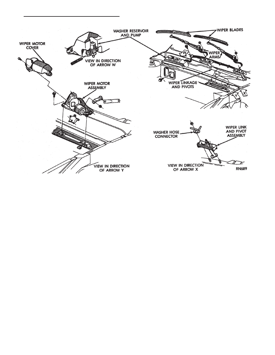
Fig. 21 Windshield Wiper Motor and Linkage—AP BODY

Ä

WINDSHIELD WIPER AND WASHER SYSTEMS

8K - 11

INTERMITTENT WINDSHIELD WIPER MOTOR AND SWITCH SERVICE

PROCEDURES

INDEX

page

page

Intermittent Windshield Wiper Switch Tests

. . . . . 12

Intermittent Wipe Switch Test

. . . . . . . . . . . . . . . 14

Intermittent Wiper Function Tests

. . . . . . . . . . . . 14

Intermittent Wiper Motor System Test

. . . . . . . . . 12

Pulse Intermittent Windshield Wiper Controller

(PIWWC) . . . . . . . . . . . . . . . . . . . . . . . . . . . . . . 15

Standard Wiper Switch Test

. . . . . . . . . . . . . . . . 14

Wiper Switch Service Procedure

. . . . . . . . . . . . . 15

INTERMITTENT WIPER MOTOR SYSTEM TEST

Intermittent Wiper Motor Service Procedures for

diagnosis of problems which do not involve the delay
function, refer to the Two-Speed Motor Function
Tests. The two-speed functions of all wiper motors
are identical.

If a problem occurs, only in the DELAY mode, the

following tests are to be performed.

INTERMITTENT WINDSHIELD WIPER SWITCH
TESTS

WARNING: ON VEHICLES EQUIPPED WITH AIR-
BAG, SEE GROUP 8M, RESTRAINT SYSTEMS FOR
STEERING WHEEL OR COLUMN REMOVAL PROCE-
DURES.

The intermittent wipe function on AC, AG, AJ and

AY vehicles is controlled by the body controller, lo-
cated in the passenger compartment behind the right
side kick panel (Fig. 22). If the body controller is de-
termined to be the problem, refer to Group 8E, In-
strument

Panels

and

Gauges,

for

replacement

procedures.

CONDITION: WIPERS DO NOT COME ON
WHEN THE SWITCH IS IN DELAY POSITION

PROCEDURE

(1) Disconnect 25-way connector (blue) from the

body controller.

(2) Place wiper control switch in maximum DE-

LAY position.

(3) Connect positive lead of voltmeter to pin 9 of

connector (blue) and negative lead to the good
ground.

(a) If voltmeter reads 0, check control switch and

wiring for an open circuit.

(b) If voltmeter reads 10 to 15 volts, proceed to

step 4.
(4) Connect positive lead of voltmeter to pin 22 of

blue connector and negative lead to a good ground.

(a) If voltmeter reads 0, check fuses and wiring

for an open circuit.

(b) If voltmeter reads 10 to 15 volts, reconnect

body controller and proceed to step 5.
(5) Connect positive lead of voltmeter to pin 24 of

blue connector and negative lead to the metal case of
the body controller. Disconnect wiring harness from
wiper motor. Set control switch to the minimum de-
lay mode.

(a) If voltmeter reads 0, check wiring from the

intermittent wipe switch to body controller for an
open circuit.

(b) If voltmeter reads 10 to 15 volts, proceed to

step 6.
(6) Connect voltmeter to pin L of the Intermittent

wiper switch. Place intermittent wiper switch in the
Max. Delay position.

(a) If voltmeter reads zero volts, change the in-

termittent wiper switch.

(b) If voltmeter reads 10-15 volts, check the wir-

ing harness from the intermittent wiper switch to
the wiper motor for an open circuit.
(7) If all tests above have been performed and the

problem was not found, replace the body controller.

Fig. 22 Body Controller Location

8K - 12

WINDSHIELD WIPER AND WASHER SYSTEMS

Ä

CONDITION: WIPERS START TO WIPE, BUT
STOP BEFORE ONE COMPLETE CYCLE AND
DO NOT RETURN TO PARK POSITION

PROCEDURE

(1) Verify that motor will park when the column

switch is put in the OFF position.

(2) Set wiper control switch to maximum DELAY

and allow motor to run until it stops during the wipe
cycle. When motor stops, disconnect 25-way blue con-
nector from the body controller.

(3) Connect positive lead of voltmeter to pin 20 of

blue connector and negative lead to the metal case of
the body controller.

(a) If voltmeter reads 0, check wiring for an open

circuit.

(b) If voltmeter reads 10 to 15 volts, proceed to

step 4.
(4) Using an ohmmeter or continuity tester;

(a) Check for continuity between pins 20 and 24

of blue connector of the body controller.

(b) Reverse ohmmeter leads on pins 20 and 24,

again checking for continuity.

(c) If continuity between pins 20 and 24 is not

observed in both steps a and b, replace the body
controller.

CONDITION: EXCESSIVE DELAY OF MORE
THAN 30 SECONDS OR INADEQUATE
VARIATION IN DELAY

PROCEDURE

(1) Variations in delay should be as follows:

(a) Minimum delay control to extreme counter-

clockwise position before first detent of 1/2 to 2 sec-
onds.

(b) Maximum delay control to extreme clockwise

position before OFF detent of 15 to 25 seconds.
(2) If there is excessive delay or no variations in

delay, remove the wiper motor wiring harness while
the motor is parked in the OFF position.

(3) Remove 25-way blue connector from the body

controller.

(4) Set wiper control switch to maximum DELAY

position.

(5) With ignition switch in ON position, measure

voltage between pin 9 of black connector and a good
ground.

(a) If voltmeter reads 0, proceed to step 6.
(b) If voltmeter reads 10 to 15 volts, proceed to

step 7.
(6) Set wiper control switch to minimum DELAY

position and measure voltage between pin 9 of blue
connector and a good ground. If voltmeter reads 0,
check for an open circuit in the intermittent wipe
wiring harness.

(7) Remove wiper motor circuit fuse.

(8) Using an ohmmeter, measure the resistance be-

tween pins 9 and 22 of the body controller 25-way
black connector. Set the wiper control switch first to
minimum DELAY and then maximum DELAY.

(a) If resistance reading at minimum DELAY

setting is between 0 and 15 ohms, and at maxi-
mum DELAY setting the resistance is between
240,000 and 400,000 ohms, replace the body con-
troller.

(b) If the resistance values above are not ob-

tained, replace the wiper control switch.

CONDITION: WIPERS DO NOT RUN
CONTINUALLY WHEN WASH CONTROL IS
OPERATED DURING DELAY MODE

PROCEDURE

(1) Disconnect 25-way blue connector from the

body controller

(2) Using a voltmeter, connect the positive lead to

pin 10 of the (Black) connector. Connect negative
lead to the body computer metal case.

(3) Set wiper control switch to DELAY position.
(4) Depress wash switch.
(5) If voltage reads 0, check switch relay and wir-

ing.

(6) If voltage is between 10 and 15 volts, the prob-

lem is in the body controller.

CONDITION: IN DELAY MODE, WIPERS RUN
CONTINUALLY WHEN WASH IS OPERATED
BUT DO NOT PROVIDE FOUR EXTRA WIPES
WHEN WASH CONTROL IS RELEASED

PROCEDURE

Replace body controller.

CONDITION: WIPERS START ERRATICALLY
DURING DELAY MODE

PROCEDURE

(1) Verify that the ground connection at the in-

strument panel is making a good connection, free
from paint and is tight.

(2) Verify that the motor ground strap is making

good contact and that the motor mounting bolts are
tight.

(3) Verify that the wiring connections to the body

controller, wiper motor, and wiper motor switch are
tight and free of corrosion.

(4) If condition is not corrected, problem is with

the body controller

Ä

WINDSHIELD WIPER AND WASHER SYSTEMS

8K - 13

INTERMITTENT WIPER FUNCTION TESTS

CONDITION: EXCESSIVE DELAY OF MORE
THAN 30 SECONDS OR INADEQUATE
VARIATION IN DELAY

PROCEDURE

Variations in delay should be as follows:
(1) Minimum delay control to extreme counter-

clockwise position before first detent of one half to
two seconds.

(2) Maximum delay control to extreme clockwise

position before off detent of ten to thirty seconds.

(3) If there is excessive delay or no variations in

delay proceed to intermittent wipe switch test.

CONDITION: IN DELAY MODE WIPERS RUN
CONTINUALLY WHEN WASH IS OPERATED
BUT DO NOT PROVIDE AN EXTRA WIPE
WHEN THE WASH CONTROL IS RELEASED

PROCEDURE

Replace the control unit.

CONDITION: WIPERS START ERRATICALLY
DURING DELAY MODE

PROCEDURE

(1) Verify that the ground connection at the in-

strument panel is making good connection, free from
paint and is tight.

(2) Verify that the motor ground strap is making

good contact and that the motor mounting bolts are
tight.

(3) Verify that the wiring ground connections for

the intermittent wipe control unit and the wiper
switch are tight.

(4) If condition is not corrected, replace control

unit.

STANDARD WIPER SWITCH TEST

AP BODY

To test the switch, first disconnect the switch wires

from the body wiring in the steering column. Using
an ohmmeter, test for continuity between the termi-
nals of the switch, as indicated in the following con-
tinuity chart. The identity of each terminal is shown
in Fig. 23.

INTERMITTENT WIPE SWITCH TEST

AC AND AY BODIES

To test the switch, first disconnect the switch wires

from the body wiring in the steering column. Using
an ohmmeter, test for continuity between the termi-
nals of the switch, as indicated in the following con-
tinuity chart. The identity of each terminal is shown
in Fig. 24.

For test purposes, the first position is the OFF po-

sition, next is the slide for the DELAY wipe. LOW is
the next detent position and HIGH is the full coun-
terclockwise detent position.

In any wiper mode, if the knob is pushed all the

way in, the washer circuit will be completed.

AG AND AJ BODIES

To test the switch, remove switch pod from instru-

ment panel. Using an ohmmeter, test for continuity
between the terminals of the switch, as indicated in
the following continuity chart (Fig. 25).

Fig. 23 Standard 2-Speed Wiper Switch Test

Fig. 24 Multi-Function Switch Connector and

Intermittent Wipe Continuity

8K - 14

WINDSHIELD WIPER AND WASHER SYSTEMS

Ä


Content   ..  330  331  332  333   ..