Chrysler Le Baron, Dodge Dynasty, Plymouth Acclaim. Manual - part 266


  Index      Chrysler     Chrysler Le Baron, Dodge Dynasty, Plymouth Acclaim - service repair manual 1993 year


Search            


Content   ..  264  265  266  267   ..


Chrysler Le Baron, Dodge Dynasty, Plymouth Acclaim. Manual - part 266


(2) Adjust belt tension by applying torque to

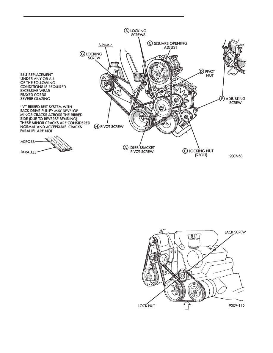
square hole C on idler bracket. Adjust tension to
specification given in Belt Tension Chart.

(3) Tighten in order, first, locking screws B then

pivot screw A to 54 N

Im (40 ft. lbs.).

POWER STEERING PUMP—S TYPE

(1) From on top of the vehicle loosen locking screw G.
(2) From under the vehicle loosen the pivot screw

and pivot nut H .

(3) After installing a new belt adjust belt tension

with 1/2 in. breaker bar installed in adjusting
bracket. See tension specification in chart.

(4) Tighten locking screw G to 54 N

Im (40 ft. lbs.).

(5) Tighten pivot screw H and the pivot nut to 54

N

Im (40 ft. lbs.)

GENERATOR BELT

(1) Loosen T-Bolt locking nut E and adjusting

screw F to remove and install Poly V belt and/or ad-
just belt tension.

(2) Tighten adjusting screw F to adjust belt tension

to specification shown in Belt Tension Chart.

(3) Tighten T-Bolt locking nut E to 54 N

Im (40 ft.

lbs.).

3.0L ENGINE BELTS REMOVE/INSTALL AND
ADJUST

AIR CONDITIONING BELT

To remove and install the air conditioning com-

pressor drive belt, first loosen the idler pulley lock
nut, then turn the adjusting screw to raise or lower
the idler pulley (Figs. 3 and 4).

To adjust the air conditioning drive belt, loosen

the idler pulley nut (Fig. 3) and adjust belt tension

Fig. 2 Accessory Drive Belts—2.2 and 2.5L Engines

Fig. 3 Accessory Drive Belts—3.0L Engine

Ä

COOLING SYSTEM

7 - 25

by tightening adjusting screw (Figs. 3 and 4 ).
Tighten pulley nut to 54 N

Im (40 ft. lbs.) after ad-

justment.

GENERATOR/POWER STEERING PUMP BELT

The Poly-V generator/power steering pump belt is

provided with a dynamic tensioner (Fig. 5) to main-
tain proper belt tension. To remove or install this
belt, Release tension by rotating the tensioner clock-
wise

3.3/3.8L AND TURBO III ENGINE ACCESSORY
DRIVE BELT REMOVE AND INSTALL

GENERATOR, POWER STEERING PUMP, AIR

CONDITIONING COMPRESSOR AND WATER

PUMP DRIVE BELT

The Poly-V Drive belt is provided with a dynamic

tensioner (Figs. 7 and 8) to maintain proper belt ten-
sion. To remove or install this belt.

(1) Raise vehicle on hoist.
(2) Remove right front splash shield.
(3) Release tension by rotating the tensioner clock-

wise (Figs. 7 and 8).

(4) Reverse above procedure to install.

Fig. 5 Release Belt Tensioner

Fig. 6 Belt Tension Chart

Fig. 4 Air Conditioning Belt Idler

7 - 26

COOLING SYSTEM

Ä

Fig. 7 Accessory Drive Belt—2.2L Turbo III Engine

Fig. 8 Accessory Drive Belt—3.3/3.8L Engines

Ä

COOLING SYSTEM

7 - 27

ENGINE BLOCK HEATER

DESCRIPTION AND OPERATION

On all models an engine block heater is available as

an optional accessory. The heater, operated by ordinary
house current (110 Volt A.C.) through a power cord and
connector behind the radiator grille, provides easier
engine starting and faster warm-up when vehicle is
operated in areas having extremely low temperatures.
The heater is mounted in a core hole (in place of a core
hole plug) in the engine block, with the heating ele-
ment immersed in coolant (Fig. 9).

The power cord must be secured in its retainer

clips, and not positioned so it could contact link-
ages or exhaust manifolds and become damaged.

If unit does not operate, trouble can be in either the

power cord or the heater element. Test power cord for
continuity with a 110-volt voltmeter or 110-volt test
light; test heater element continuity with an ohmmeter
or 12-volt test light.

REMOVAL

(1) Drain coolant from radiator and cylinder block.

Refer to Cooling System Drain, Clean, Flush and Re-
fill of this section for procedure.

(2) Detach power cord plug from heater.
(3) Loosen screw in center of heater. Remove

heater assembly.

INSTALLATION

(1) Thoroughly clean core hole and heater seat.
(2) Insert heater assembly with element loop posi-

tioned upward.

(3) With heater seated, tighten center screw se-

curely to assure a positive seal.

(4) Fill cooling system with coolant to the proper

level, vent air, and inspect for leaks. Pressurize sys-
tem with Radiator Pressure Tool before looking for
leaks.

Fig. 9 Engine Block Heater

7 - 28

COOLING SYSTEM

Ä


Content   ..  264  265  266  267   ..