Chrysler Le Baron, Dodge Dynasty, Plymouth Acclaim. Manual - part 246


  Index      Chrysler     Chrysler Le Baron, Dodge Dynasty, Plymouth Acclaim - service repair manual 1993 year


Search            


Content   ..  244  245  246  247   ..


Chrysler Le Baron, Dodge Dynasty, Plymouth Acclaim. Manual - part 246


BRAKES

CONTENTS

page

page

BENDIX ANTILOCK 4 BRAKE SYSTEM

. . . . . . 12

GENERAL INFORMATION . . . . . . . . . . . . . . . . . . 1

HYDRAULIC SYSTEM CONTROL VALVES

. . . 10

SERVICE ADJUSTMENTS

. . . . . . . . . . . . . . . . . . 3

GENERAL INFORMATION

Throughout this group, references may be made to

a particular vehicle by letter or number designation.
A chart showing the break down of these designa-
tions is included in the Introduction Section at the
front of this service manual.

Standard brake equipment consists of:

• Double pin floating caliper disc front brakes.

• Rear automatic adjusting drum brakes.

• Differential valve with a brake warning switch.

• Master cylinder.

• Vacuum power booster.

• Double pin floating caliper rear disc brakes are
available on some models.

The Bendix Antilock 4 Brake System, uses the fol-

lowing standard brake system components. Master
cylinder, power booster, caliper assemblies, braking
discs, pedal assembly, brake lines and hoses. The
unique parts of the Bendix Antilock 4 Brake System
consists of the following components, modulator as-
sembly, unique proportioning valves, unique junction
block, wheel speed sensors, tone wheels, and elec-
tronic control unit. These components will be de-
scribed in detail in the Bendix Antilock 4 Brake
System section in this service manual supplement.

The hydraulic system, (Fig. 1) on the Bendix Anti-

lock 4 brake system is diagonally split. Diagonally
split hydraulic brake systems, have the left front and
right rear brakes on one hydraulic system and the
right front and left rear on the other. A diagonally
split hydraulic brake system, will maintain half of
the vehicles braking capability if there is a failure in
either half of the hydraulic system.

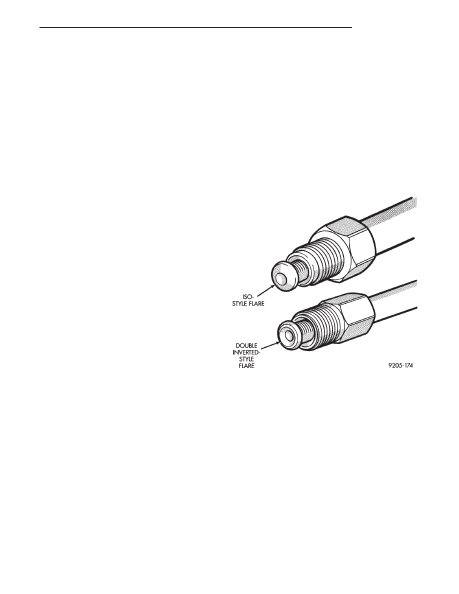
The Bendix Antilock 4 Brake System uses two

types of brake line fittings and tubing flares on the
modulator assembly (Fig. 1). The different types are
the ISO style and double wall style with their corre-
sponding fittings at different joint locations. See (Fig.
2) for specific joint locations and type of tubing
flares.

CAUTION: When servicing a vehicle, sheet metal
screws, bolts or other metal fastener cannot be in-
stalled in a shock tower to take the place of any
original plastic clip. Also, NO holes can be drilled
into the front shock tower in the area shown in (Fig.
3), for installation of any metal fasteners into the
shock tower.

Because of minimum clearance in this area, (Fig.

3) installation of metal fasteners could damage the
coil spring coating and lead to a corrosion failure of
the spring. If a plastic clip is missing, lost or broken
during servicing a vehicle, replace only with the
equivalent part listed in the Mopar parts catalog.

Fig. 1 Identifying Hydraulic Brake Tubing Flares

Ä

BRAKES

5 - 1

Fig. 2 Bendix Antilock 4 Brake Tube Routing And Fitting Locations

Fig. 3 Shock Tower To Spring Minimum Clearance

Area

5 - 2

BRAKES

Ä

SERVICE ADJUSTMENTS

INDEX

page

page

Bleeding Bendix Antilock Brake System

. . . . . . . 3

Master Cylinder Fluid Level

. . . . . . . . . . . . . . . . . . 3

Testing for Fluid Contamination

. . . . . . . . . . . . . . . 4

MASTER CYLINDER FLUID LEVEL

Check master cylinder reservoir brake fluid level a

minimum of two times a year.

Master cylinder reservoirs are marked with the

words fill to bottom of rings indicating proper fluid
level (Fig. 4).

Use only Mopar

t brake fluid or an equivalent from

a sealed container. Brake fluid must conform to DOT
3, specifications.

Use only brake fluid that was stored in a tightly-

sealed container.

CAUTION: DO NOT use petroleum-based fluid be-
cause seal damage in the brake system will result.

CAUTION: DO NOT use brake fluid with a lower
boiling point, as brake failure could result during
prolonged hard braking.

If necessary add only an approved brake fluid to

master cylinder fluid reservoir until filled to the
proper level. Correct master cylinder fluid reservoir
fill level is to the bottom of the primary reservoir
split ring.

BLEEDING BENDIX ANTILOCK 4 BRAKE SYSTEM

CAUTION: When bleeding the Bendix Antilock 4
Brake System hydraulic circuits, refer to the Bendix
Antilock 4 Brake System bleeding procedure in this
service manual supplement.

BASE BRAKE SYSTEM BLEEDING
PROCEDURE

CAUTION: The base brakes hydraulic system, on a
vehicle equipped with a Bendix Antilock 4 Brake
System, can NOT be bled using a brake hydraulic
system pressure bleeder. This type of pressure
bleeding equipment, does not develop the pressure
required in the brake hydraulic system, to ade-
quately bleed all trapped air. The only approved
method of bleeding the base brakes hydraulic sys-
tem, on vehicles equipped with a Bendix Antilock 4
Brake System, is the manual procedure of pressur-
izing the hydraulic system using constant moderate
to heavy foot pressure on the brake pedal.

When bleeding brake hydraulic systems, some air

may be trapped in brake lines or valves as far as ten
feet from the bleeder screw (Fig. 5). Therefore, it is
essential to have a fast flow of a large volume of
brake fluid when bleeding the brakes. This will en-
sure all trapped air is completely bled out of the
brakes hydraulic system.

To bleed the base brake hydraulic system. Attach a

clear plastic hose to the bleeder screw starting at the
right rear wheel and feed the hose into a clear jar
containing fresh brake fluid (Fig. 6).

The following wheel sequence when bleeding the

base brakes hydraulic system should be used. This
sequence will ensure adequate removal of all trapped
air from the hydraulic system.
• Right rear wheel

• Left front wheel

Fig. 4 Master Cylinder Fluid Level

Fig. 5 Trapped Air in Brake Line

Ä

BRAKES

5 - 3

• Left rear wheel
• Right front wheel

(1) Pump brake pedal three or four times, then

hold a constant moderate to heavy foot pressure on
the brake pedal.

CAUTION: Just cracking the bleeder screw often re-
stricts fluid flow, and a slow, weak fluid discharge
will NOT get all the air out.

(2) Open bleeder screw (Fig. 7) at least 1 full turn.

When bleeder screw opens, brake pedal will drop to
the floor.

(3) Close bleeder screw. Release brake pedal off

floor only after bleeder screw is completely closed.

(4) Repeat steps 1 through 3, four or five times, at

each bleeder screw. This should pass a sufficient
amount of brake hydraulic fluid to expel all trapped
air. Be sure to monitor brake fluid level in master
cylinder fluid reservoir. It must stay at a level that
will not allow air to re-enter the hydraulic system
through the master cylinder.

After 4 to 8 ounces of hydraulic fluid has been bled

from the bleeder screw at this wheel, and an air-free
flow has been maintained, a good bleed is indicated.

Repeat above procedure at all other remaining

bleeder screws, while checking brake pedal for

travel. If brake pedal travel is still excessive or has
not improved, enough brake fluid has not passed
through the hydraulic system to expel all trapped
air. Be sure to monitor brake fluid level in the mas-
ter cylinder brake fluid reservoir. It must stay at the
proper level so air will not be allowed to re-enter the
brake system through the master cylinder.

Test drive vehicle to be sure brakes are operating

correctly and that pedal is not spongy.

TESTING FOR FLUID CONTAMINATION

Indications of fluid contamination are swollen or

deteriorated rubber parts.

Swollen rubber parts indicate the presence of petro-

leum in the brake fluid.

To test for contamination, put small amount of

drained brake fluid in clear glass jar. If fluid sepa-
rates into layers, there is mineral oil contamination.

If contaminated, drain and thoroughly flush sys-

tem. Replace master cylinder, proportioning valve,
caliper seals, wheel cylinder seals and all hoses.

Fig. 6 Proper Method for Purging Air From Brake

System

Fig. 7 Open Bleeder Screw at Least One Full Turn

(Typical)

5 - 4

BRAKES

Ä


Content   ..  244  245  246  247   ..