Chrysler Le Baron, Dodge Dynasty, Plymouth Acclaim. Manual - part 228


  Index      Chrysler     Chrysler Le Baron, Dodge Dynasty, Plymouth Acclaim - service repair manual 1993 year


Search            


Content   ..  226  227  228  229   ..


Chrysler Le Baron, Dodge Dynasty, Plymouth Acclaim. Manual - part 228


(16) Install wheel and tire assemblies.

(17) Tighten wheel stud nuts to 129 N

Im (95 ft-

.lbs.).

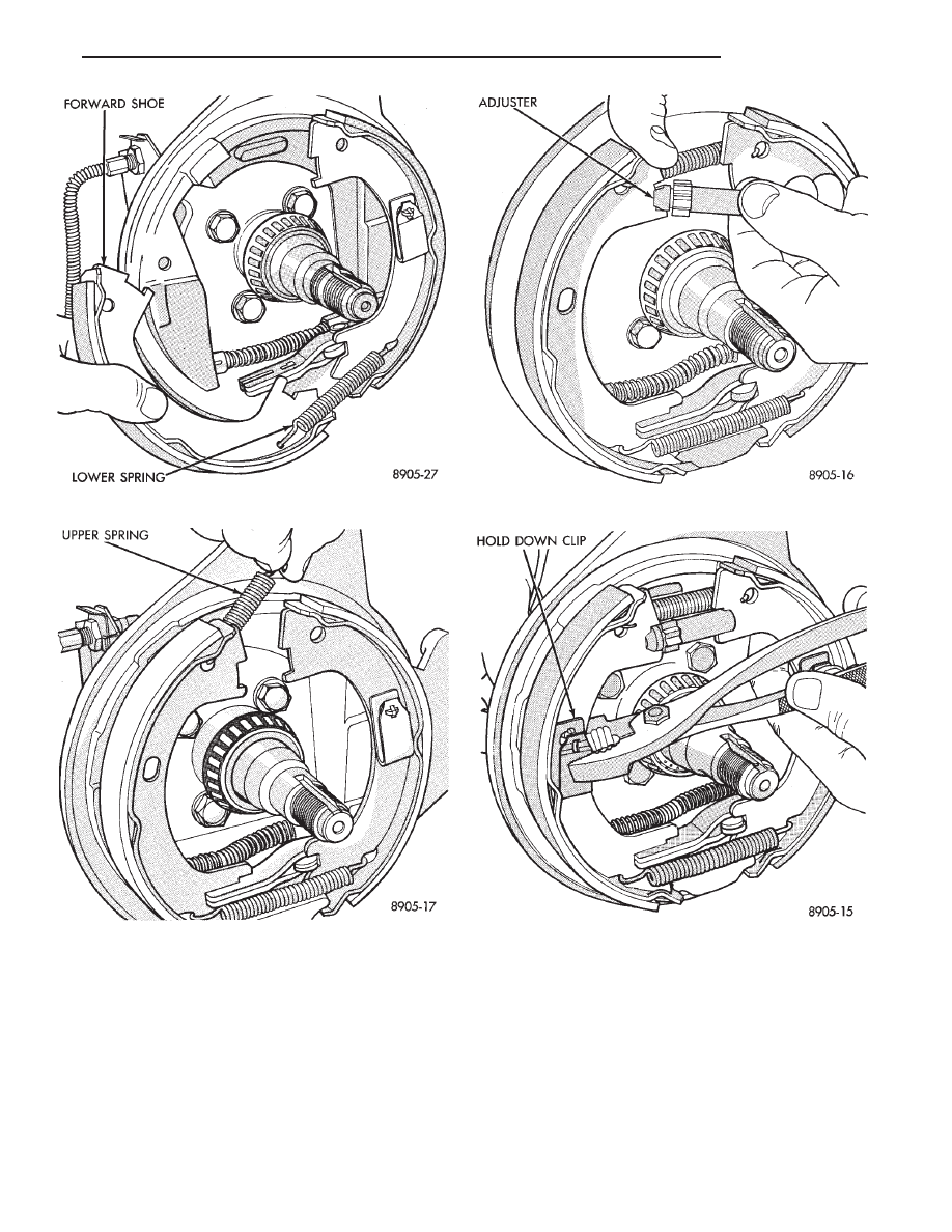
Fig. 7 Installing Lower Spring

Fig. 8 Installing Upper Spring

Fig. 9 Installing Adjuster Assembly

Fig. 10 Installing Front Parking Brake Shoe Hold-

Down Clip

Ä

BRAKES

5 - 65

MASTER CYLINDER

INDEX

page

page

Brake Fluid Level Sensor

. . . . . . . . . . . . . . . . . . 66

General Information

. . . . . . . . . . . . . . . . . . . . . . . 66

Master Cylinder Service Procedures

. . . . . . . . . . 67

Testing the Master Cylinder

. . . . . . . . . . . . . . . . . 66

GENERAL INFORMATION

The tandem master cylinder (Fig. 1) has a glass re-

inforced nylon reservoir and an anodized aluminum
body.

Do not hone the bore of the cylinder, as this will

remove the anodized surface.

The reservoir is indexed to prevent installation in

the wrong direction (Fig. 2). The cap diaphragms are
slit to allow atmospheric pressure to equalize on both
sides of the diaphragm.

The primary and secondary outlet tubes from the

master cylinder are connected to the valve mounted
under the master cylinder. The front part of this
block connects to the secondary outlet tube and sup-
plies the right rear and left front brakes. The rear
portion of the block connects to the primary outlet
tube and supplies the right front and left rear
brakes.

BRAKE FLUID LEVEL SENSOR

The Brake Fluid Level sensor is found only in the

AJ body vehicles with the visual electronic message
center. The purpose of the sensor is to provide the
driver with an early warning message that brake
fluid in master cylinder reservoir has dropped to a
below normal.

As the fluid drops below the design level the sensor

closes the warning message circuit. Approximately
15 seconds later the message BRAKE FLUID LOW
appears on the instrument panel. At this time the

master cylinder reservoir should be checked and filled
to the bottom of the rings with DOT 3 brake fluid.

To check the operation of the Brake Fluid Level

sensor, with ignition on and wiring still attache-
d,remove sensor from master cylinder and hold in
upright position. Within 30 seconds the instrument
panel message BRAKE FLUID LOW should appear.
Next invert the sensor. The instrument panel message
should turn off immediately. If the above sequence
occurs the sensor is operating properly. If the message
does not appear remove the wiring from the sensor and
using a jumper wire connect both sides of the plug. The
instrumental panel message BRAKE FLUID LOW
should appear within 30 seconds. If the message does
not appear a problem exists in the wiring or instru-
mentation. If the message does appear the sensor is
faulty and must be replaced. The Brake Fluid Level
sensor is not a repairable item (Fig. 2).

TESTING THE MASTER CYLINDER

Be sure master cylinder vents at both ports.
Apply pedal lightly with engine running and look for

fluid squirting or swirling into reservoirs.

In this master cylinder, a special baffle reduces the

amount of fluid entering the secondary reservoir only a
small disturbance may be seen.

Fig. 1 Aluminum Master Cylinder (Cutaway View)

Fig. 2 Brake Fluid Level Sensor

5 - 66

BRAKES

Ä

MASTER CYLINDER SERVICE PROCEDURES

MASTER CYLINDER REMOVAL

Disconnect primary and secondary brake tubes from

master cylinder housing. Install plugs at brake tube
outlets.

Remove 2 nuts (Fig. 3) attaching master cylinder

housing to power brake booster unit.

Slide master cylinder straight out, and away from

power brake booster unit.

BRAKE FLUID RESERVOIR REPLACEMENT

Clean master cylinder housing and brake fluid res-

ervoir.

Remove the brake fluid reservoir caps. Using a

syringe or equivalent empty brake fluid from reservoir.

Position master cylinder in vise.
Rock reservoir from side to side and remove from

master cylinder housing (Fig. 4).

Do not pry off with tool, damage to reservoir

may result.

Remove housing-to-reservoir grommets (Fig. 5).
Install new housing-to-reservoir grommets in master

cylinder housing.

Lubricate reservoir mounting area with clean brake

fluid. Place reservoir in position over grommets. Seat
reservoir with a rocking motion onto master cylinder
housing.

Be sure reservoir is positioned properly. All lettering

should be properly read from the left side of the master
cylinder (Fig. 4).

Make sure bottom of reservoir touches top of grom-

met.

BLEEDING MASTER CYLINDER

Clamp the master cylinder in a vise. Attach Bleeding

Tubes, Special Tool C-4546 to the master cylinder.
Position tubes so the outlet of the Bleeding Tubes will
be below the surface of the brake fluid when the
reservoir is filled to the proper level.

Fill both reservoirs with brake fluid conforming to

DOT 3 specifications such as Mopar or Equivalent.

Using a wooden dowel per (Fig. 6). Depress push rod

slowly, and then allow pistons to return to released
position. Repeat several times until all air bubbles are
expelled (Fig. 6).

Remove bleeding tubes from cylinder, plug outlets

and install caps.

Remove master cylinder from vise and install on

power brake vacuum booster.

It is not necessary to bleed the entire hydraulic

system after replacing the master cylinder. But
the master cylinder must have been bled and
filled upon installation.

Fig. 4 Removing Reservoir

Fig. 5 Removing Grommets

Fig. 3 Master Cylinder Mounting

Ä

BRAKES

5 - 67

INSTALLING MASTER CYLINDER

Position master cylinder over studs of power brake

unit, align push rod with master cylinder piston.

Install the master cylinder to power brake unit

mounting nuts (Fig. 4) and tighten to 28 N

Im (250 in.

lbs.) torque.

Connect brake tubes to master cylinder primary and

secondary ports. Tighten fittings to 17 N

Im (145 in-

.lbs.) torque.

POWER BRAKES

GENERAL INFORMATION

All vehicles, except non turbo charged AP bodies,

equipped with manual transmissions use a 205 mm
tandem booster. The non turbo charged manual trans-
mission equipped AP body application use a 230 mm
non-tandem booster.

The purpose of the vacuum operated power brake

booster. Is to reduce the amount of force applied to the
brake pedal by the drivers foot. To obtain the required
hydraulic pressure in the brake system to stop the
vehicle.

The power brake booster can be identified if required,

by the tag attached to the body of the booster assembly
(Fig. 1). This tag contains the following information.
The production part number of the power booster
assembly, the date it was built and who manufactured
it.

The power brake booster assembly is not a

repairable part and must be replaced as a com-
plete unit if it is found to be faulty in any way.
The power booster vacuum check valve is not
repairable but can be replaceable as an assembly.

The power brake booster is vacuum operated. The

vacuum is supplied from the intake manifold on the
engine through the power brake booster check valve
(Fig. 2).

As the brake pedal is depressed, the power boosters

input rod moves forward. This opens and closes valves
in the power booster, creating a vacuum on one side of
a diaphragm and allowing atmospheric

pressure to enter on the other. This difference in
pressure forces the output rod of the power booster
out against the primary piston of the master cylin-
der. As the pistons in the master cylinder move for-
ward this creates the hydraulic pressure in the brake
system.

Different systems and engine combinations require

different vacuum hose routings.

Fig. 6 Bleeding Master Cylinder

Fig. 1 Power Brake Booster Identification

5 - 68

BRAKES

Ä


Content   ..  226  227  228  229   ..